

Universal rack rail
a technology of universal racks and racks, applied in the field of mechanisms, can solve the problems of increasing managing loose hardware for a large system, and affecting the maintenance efficiency of rack systems, so as to reduce the cost of installing and maintaining rack systems
- Summary
- Abstract
- Description
- Claims
- Application Information
AI Technical Summary
Benefits of technology
Problems solved by technology
Method used
Image

Examples
Embodiment Construction
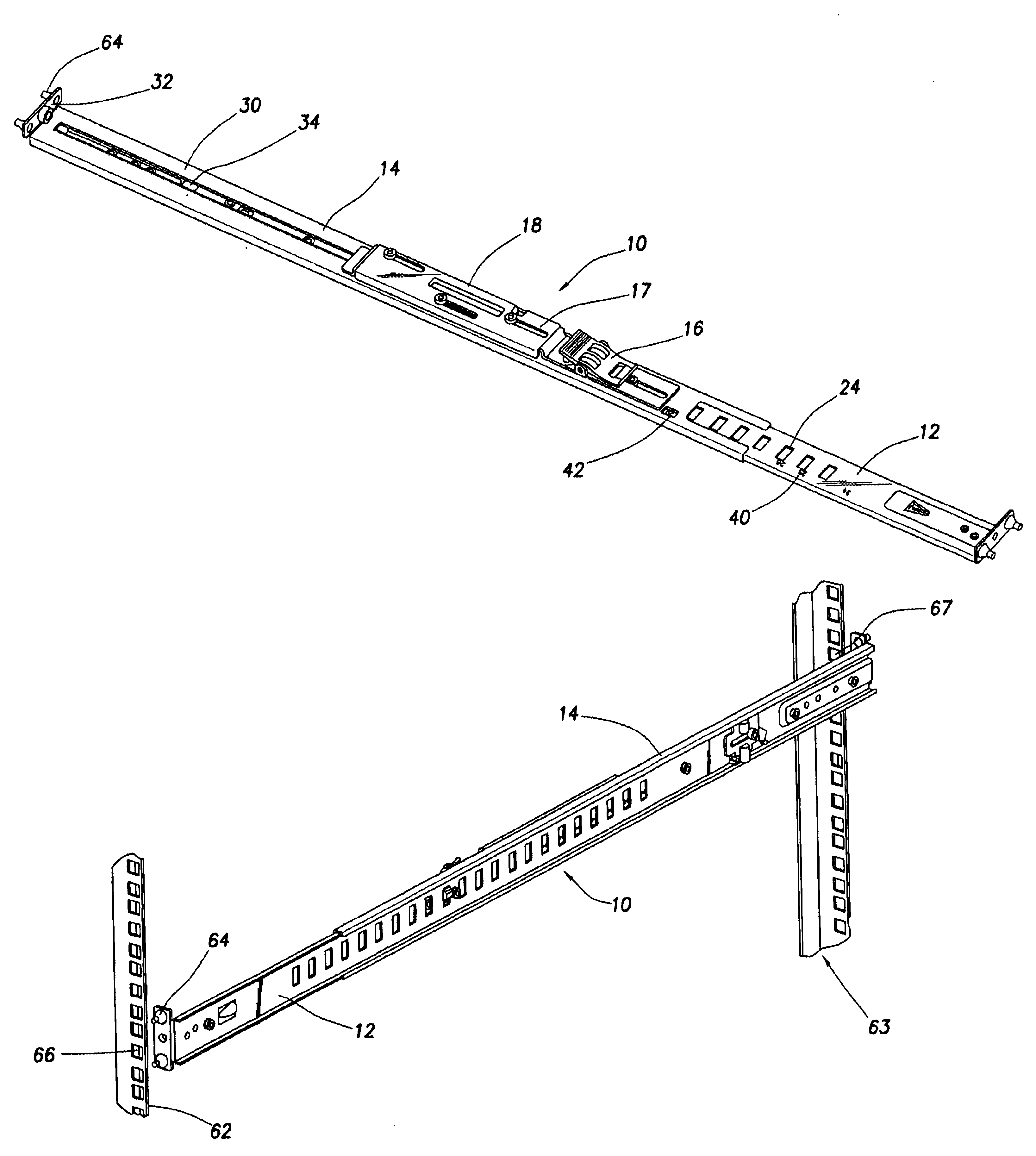
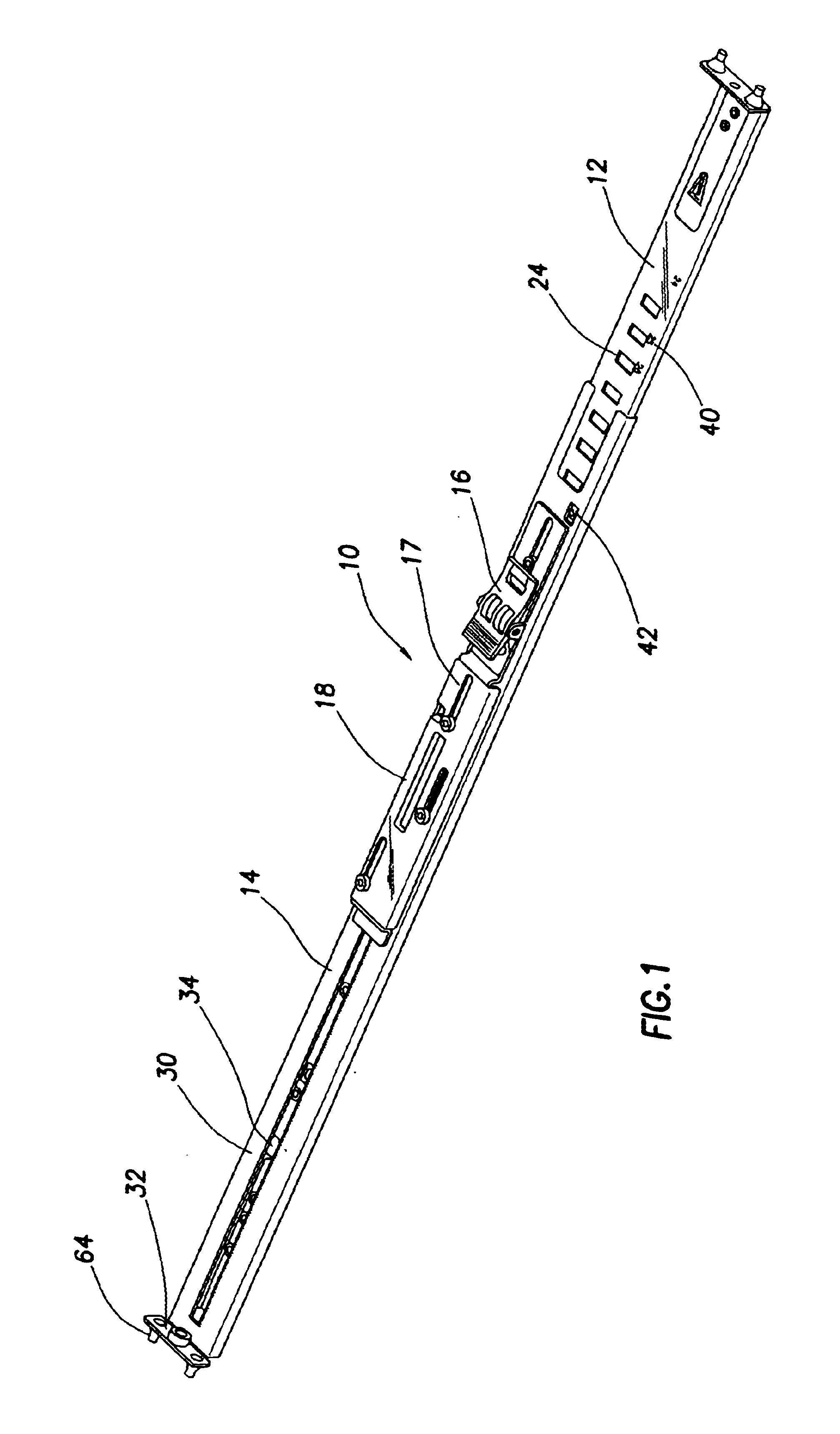
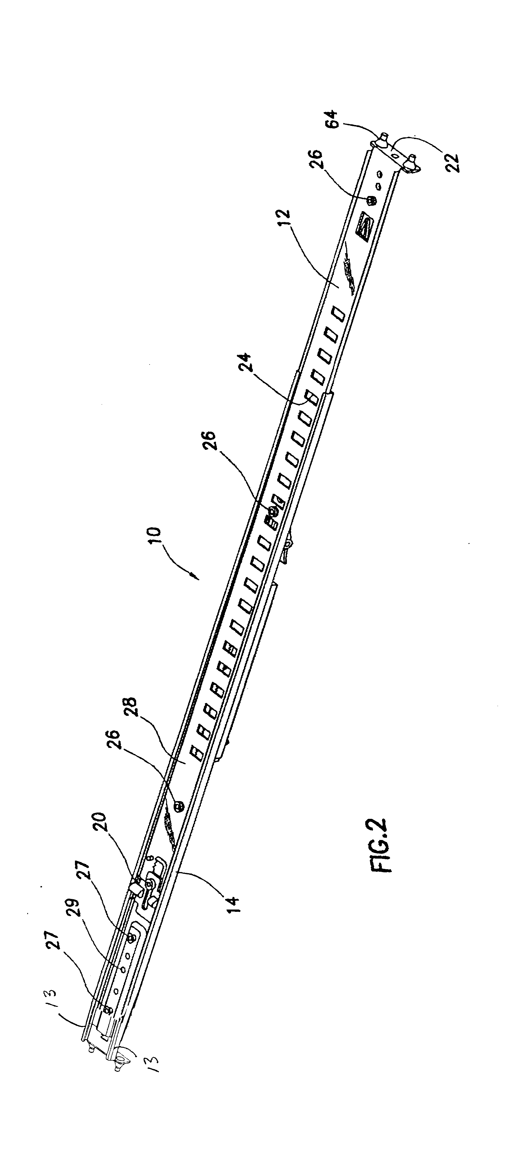
The preferred embodiments of the present invention overcome the deficiencies of the prior art noted above, by providing a rack rail assembly that can easily be used in a variety of rack types. Accordingly, one preferred embodiment of the rack rail assembly comprises inner and outer rail members that are slidingly engaged so that the rack rail assembly is adjustable lengthwise so that it can be used with various depth racks. The assembly further comprises a primary locking mechanism that locks the rails together at the desired length and is coupled to a biasing mechanism that allows the rails to be compressed for installation within a rack. Each end of the rail assembly has pins that interface with mounting holes located in the rack and are held in place without nuts or other hardware. Preferably, the pins are capable of interfacing with circular or rectangular mounting holes. The rail assembly further comprises a secondary locking mechanism that locks the inner and outer rail togeth...
PUM
 Abstract
Description
Claims
Application Information