Valve for use in wells

a valve and well technology, applied in the direction of fluid removal, valves/well accessories, sealing/packing, etc., can solve the problems of valves not being able to achieve "full bore flow", and reduce the overall production of wells

Inactive Publication Date: 2003-12-30
SCHLUMBERGER TECH CORP
View PDF20 Cites 49 Cited by
  • Summary
  • Abstract
  • Description
  • Claims
  • Application Information

AI Technical Summary

Problems solved by technology

One problem associated with producing from a well in this manner relates to the control of the flow of fluids from the well and to the management of the reservoir.
The production of water near the heel reduces the overall production from the well.
Likewise, gas coning may reduce the overall production from the well.
How

Method used


Image

  • Valve for use in wells
  • Valve for use in wells
  • Valve for use in wells

Examples


Embodiment Construction

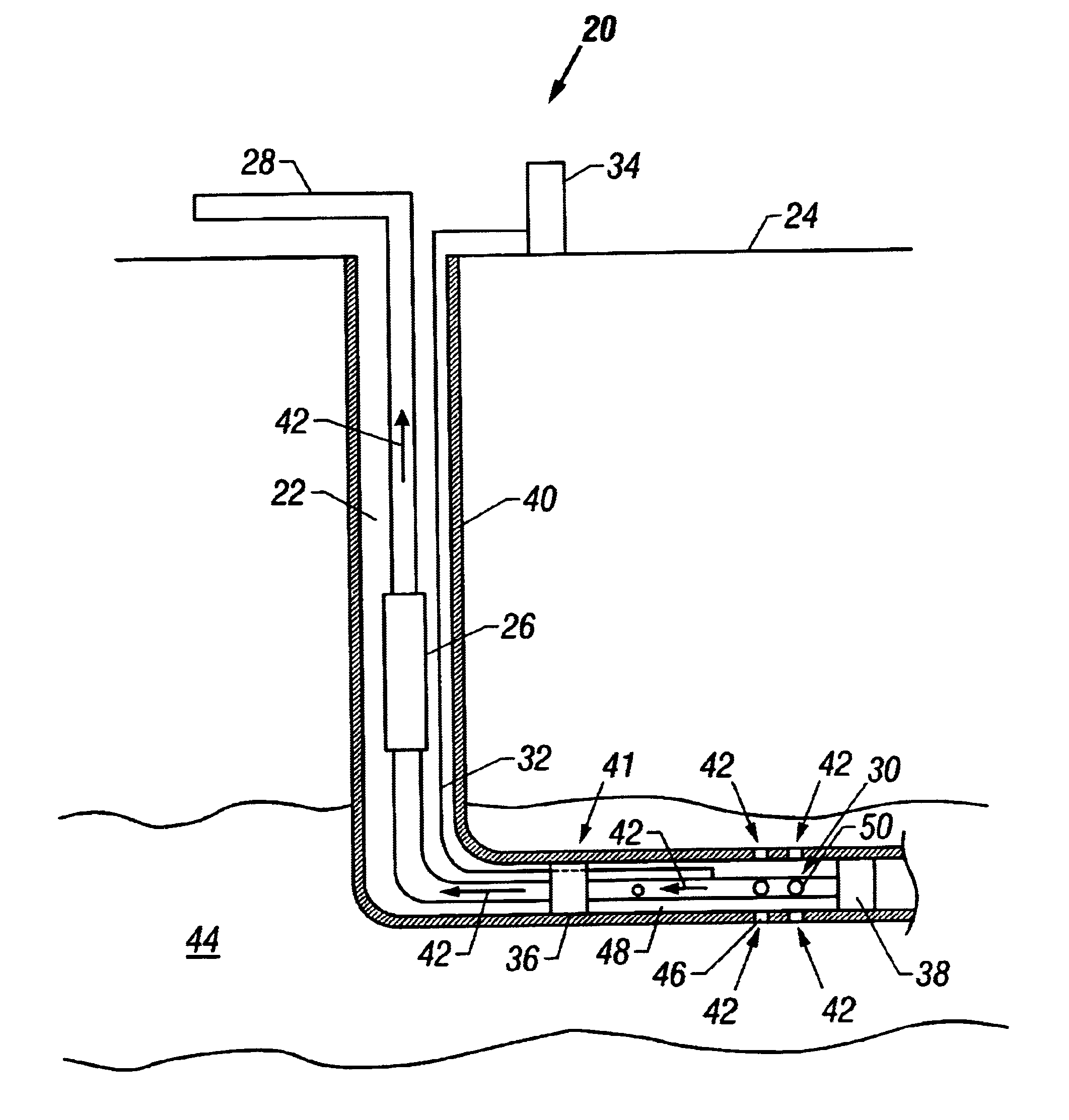
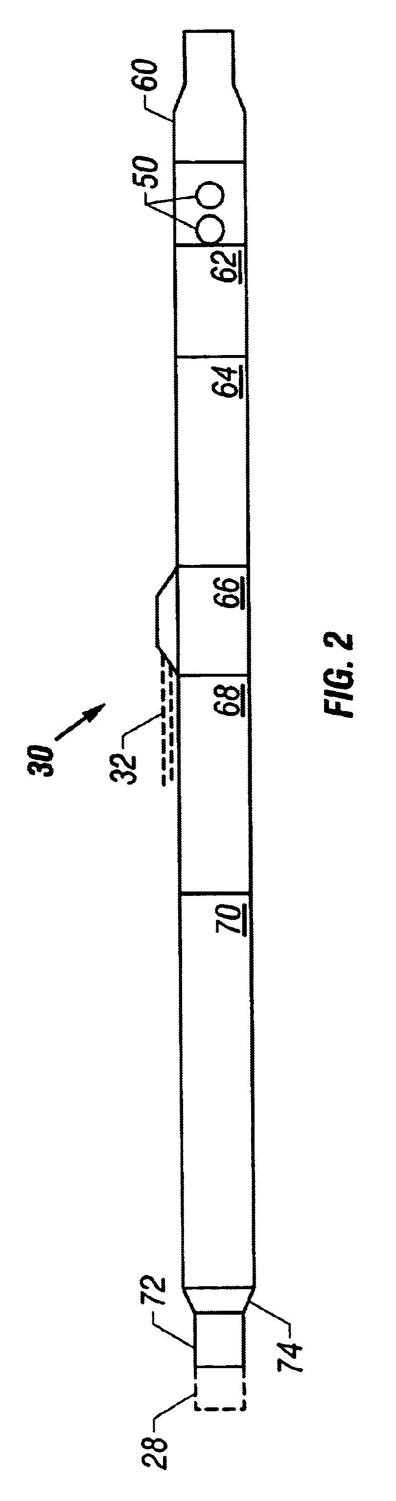
One or more specific embodiments of the present invention will be described below. In an effort to provide a concise description of these embodiments, not all features of an actual implementation may be described in the specification. It should be appreciated that in the development of any such actual implementation, as in any engineering or design project, numerous implementation-specific decisions must be made to achieve the developers' specific goals, such as compliance with system-related and business-related constraints, which may vary from one implementation to another. Moreover, it should be appreciated that such a development effort might be complex and time consuming, but would nevertheless be a routine undertaking of design, fabrication, and manufacture for those of ordinary skill having the benefit of this disclosure.

As used herein, the terms "up" and "down"; "upper" and "lower"; "upwardly"and downwardly"; and other like terms indicating relative positions above or below ...


PUM


Abstract

A valve assembly to control the intake of fluid. The valve assembly has a valve body and a valve choke disposed therein. The valve choke has a choke bore through the interior of the valve choke. The valve choke has a plurality of orifices to the choke bore spaced at intervals along the valve choke. A seal is disposed between the valve body and valve choke. The valve system is operable to position the valve choke so that the seal is positioned between the valve body and the valve choke at the intervals between the plurality of orifices.

Description

1. Field of the InventionThe present invention relates to the field of flow control. More specifically, the invention relates to a device and method for controlling the flow of fluids in a wellbore that, in one embodiment, provides for full tubing flow.2. Background of the Related ArtThe economic climate of the petroleum industry demands that oil companies continually improve their recovery systems to produce oil and gas more efficiently and economically from sources that are becoming increasingly difficult to exploit without increasing the cost to the consumer. One successful technique currently employed is the drilling of deviated wells, in which a number of horizontal wells are drilled from a central vertical borehole. In such wells, and in standard vertical wells, the well may pass through various hydrocarbon bearing zones or may extend through a single zone for a long distance. One method to increase the production of the well is to perforate the well in a number of different l...

Claims


Application Information

Patent Timeline
IPC IPC(8): E21B34/10E21B34/00E21B23/00E21B43/12E21B43/32
CPCE21B23/006E21B43/32E21B43/12E21B34/10
Inventor MCLOUGHLIN, EUGENE P.RUBINSTEIN, SCOTT A.MARTINEZ, RICARDOKOSMALA, ALEXANDRE G.E.
Owner SCHLUMBERGER TECH CORP
Why Eureka
Try Eureka