Marine hydro lift flaps

Inactive Publication Date: 2004-02-03
SMITH JOSEPH ALAN
View PDF8 Cites 27 Cited by
  • Summary
  • Abstract
  • Description
  • Claims
  • Application Information

AI Technical Summary

Benefits of technology

Flap operation devices can be powered by air, water, oil, electricity or other means. Activation device numbers per flap (107, 112) can be one or more. The flaps (101) can be extended small amount (minimally) and will generate lift. This lift, if only one flap is activated, will lift the desired boat area. Boat trim can be accomplished with no cargo movement ne

Problems solved by technology

The steering drag action will res

Method used


Image

  • Marine hydro lift flaps
  • Marine hydro lift flaps
  • Marine hydro lift flaps

Examples


Example

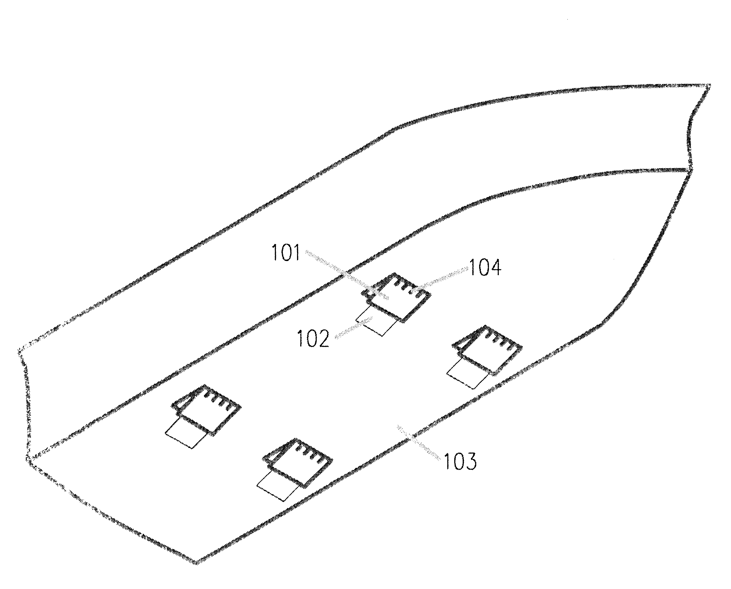
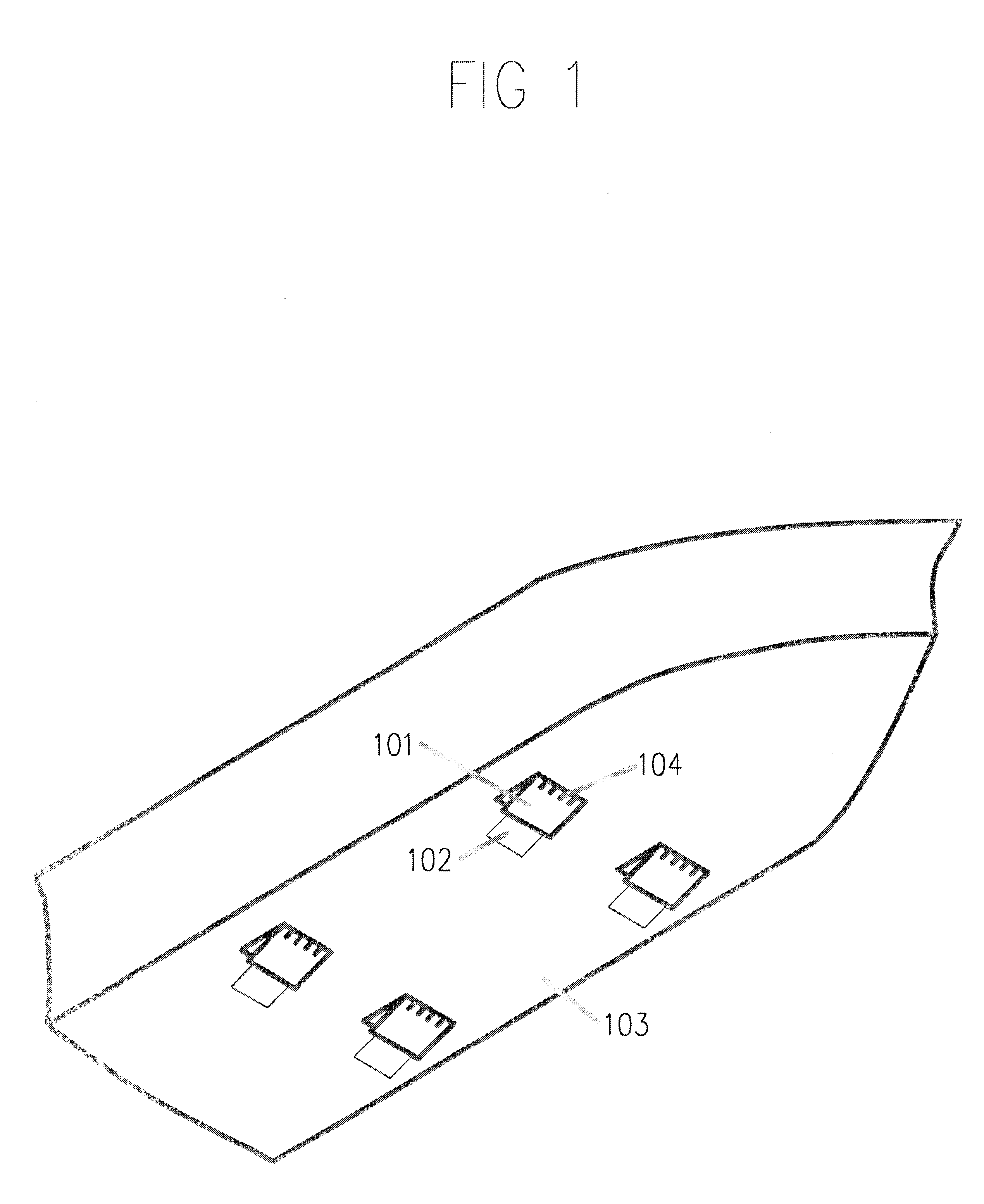
FIG. 1 shows a perspective view of a basic version of the Smith Moses Hydro Lift Flaps as installed on a boat bottom Note that the flaps (101) are fastened to the boat bottom at the forward edge, where the hinge is located. The FIG. 1 shows four flaps, however fewer or more flaps may be used. The extensions (102) are also shown in FIG. 1, and the slots (104) can be seen. The slots are openings in the flaps located a short distance from the hinges. The slot openings may be round or other shape, as desired. The flaps and the extensions are both shown in the employed positions.

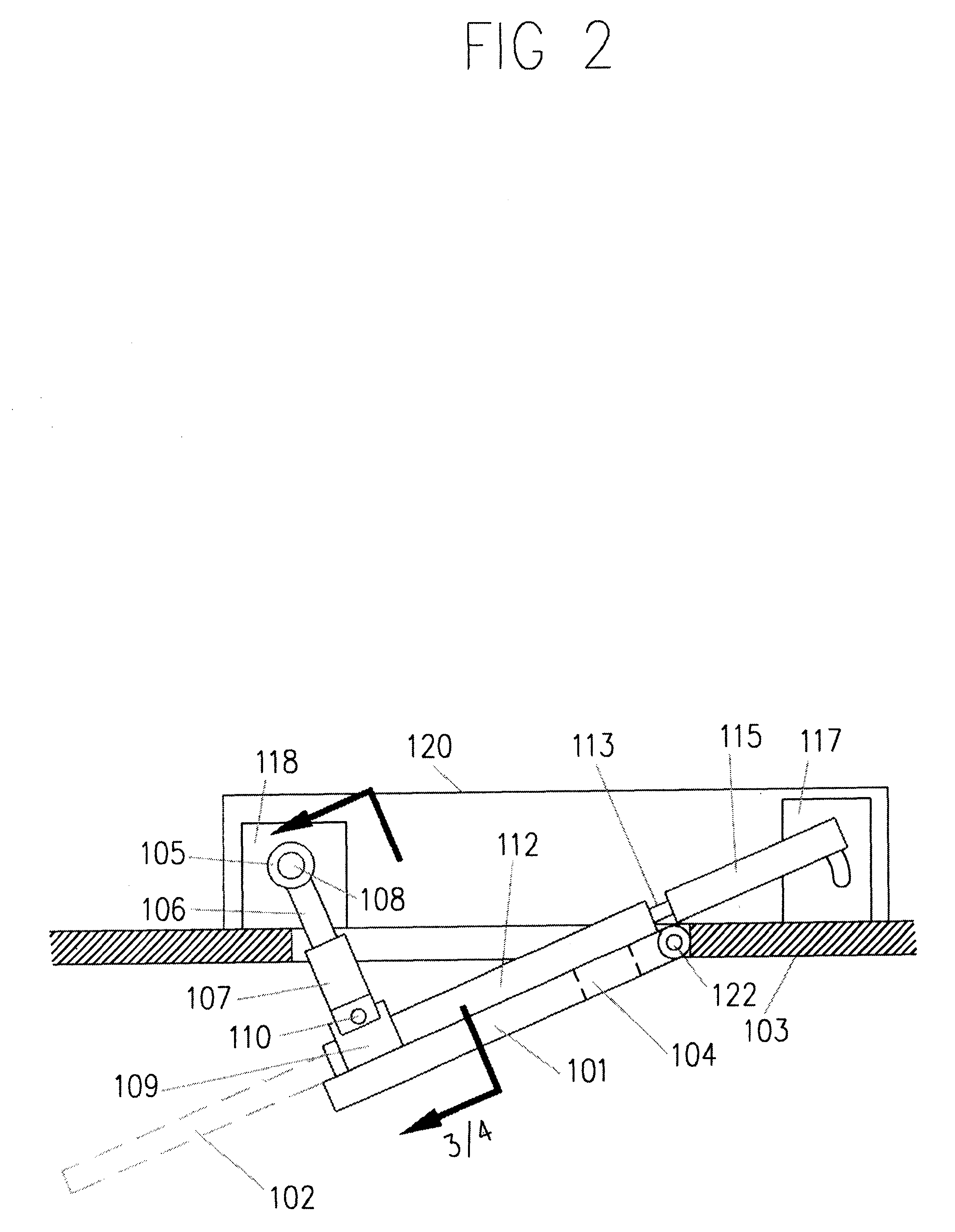
FIG. 2 is a side view of the flaps (101) shown in the extended position. The flap actuation cylinders and attaching parts are shown as (105), (106), (107), (108), (109), (110), and (118). The flap extension (102) is shown in dotted lines and the extension actuation cylinders and their attaching parts are shown as (112), (113), (115) and (117). The slots can be seen as (104) and the hinge as (122).

The entire flap ...


PUM


Abstract

The flaps (101) are fastened to the bottom of the boat, with hinges (122) and are extended under the moving boat to generate lift or cause drag. The area of the flaps (101) can be increased with extensions (102). Slots (104) are present on the flaps (101) to relieve vortexes and some drag. Lift amount can be regulated by the amount of flap presentation and by use of the extensions (102). Flaps are individually controllable or can be moved in unison. Increased drag will result from extreme extension of the flaps. The number of flaps, fastened to the boat forward of the stern, can be two, four or more if desired. Complete retraction of the flaps will result in a smooth bottom

Description

Not ApplicableFEDERALLY SPONSORED RESEARCHNot ApplicableSEQUENCE LISTING OR PROGRAMNot Applicable1. Field of InventionThis invention related to boats, specifically to a method of improving the performance of boats.2. Background of the InventionBoat bottoms have traditionally been designed to disturb the water flow around the boat, as little as possible.This smooth flow did little to contribute positive forces which would enhance the boats speed or decrease propulsion fuel consumption.Steering is primarily done with a deflected plane (rudder) installed at the rear of the boat,No external method was available to level an uneven or listing boat, caused by damage or improper loading.Stopping a boat was done primarily by reversing the propulsion (propellers) which caused severe strains and possible damage to the boat.BACKGROUND OF INVENTION-OBJECTS AND ADVANTAGESAccordingly several objects and advantages of the present invention are:(a) the Smith Moses Hydro Lift flaps, when partially ex...

Claims


Application Information

Patent Timeline
IPC IPC(8): B63B1/22B63B1/16
CPCB63B1/22Y02T70/121B63H25/44Y02T70/10
Inventor SMITH, JOSEPH ALAN
Owner SMITH JOSEPH ALAN
Why Eureka
Try Eureka