
Retractable composite impeller assembly

a composite impeller and assembly technology, applied in the field of aerospace, can solve the problems of aerodynamic instability, large rotor blade span, dimension and non-uniformity of blade sections, etc., and achieve the effect of generating lift, easy modification, and allowing the angle of attack of the impeller blade assembly to be altered

Inactive Publication Date: 2013-09-26
CARABALLOSO ESTEBAN A
View PDF2 Cites 2 Cited by
  • Summary
  • Abstract
  • Description
  • Claims
  • Application Information

AI Technical Summary

Benefits of technology

The present invention is a retractable blde system for wind turbines that uses composite materials to bear the primary stresses during operation. This reduces the loads experienced by the remaining rigid support structure and reduces the amount of creep experienced by the system. The use of flexible and strong composite materials makes the blades easy to refit or refurbish without replacing the entire system. The components of the invention include an impeller blade assembly, a rotor hub, rotor axle assembly, retraction reel assembly, blade internal support structure, release cable assembly, helical ribbon assembly, exterior sleeve assembly, blade casing assembly, and extendable zipper mechanism.

Problems solved by technology

In order to be effective conventional rotor blades often require very large rotor blade spans.
This reduction of dimension and non uniformity of the blade sections creates aerodynamic instabilities and it is not desirable.
These designs are too cumbersome and do not provide the required compactability of the rotor blades to be used practically by road worthy vehicles.

Method used


Image

  • Retractable composite impeller assembly
  • Retractable composite impeller assembly
  • Retractable composite impeller assembly

Examples


Embodiment Construction

[0058]A technical description of the major subassemblies of the invention will follow,

02. Rotor Blades:

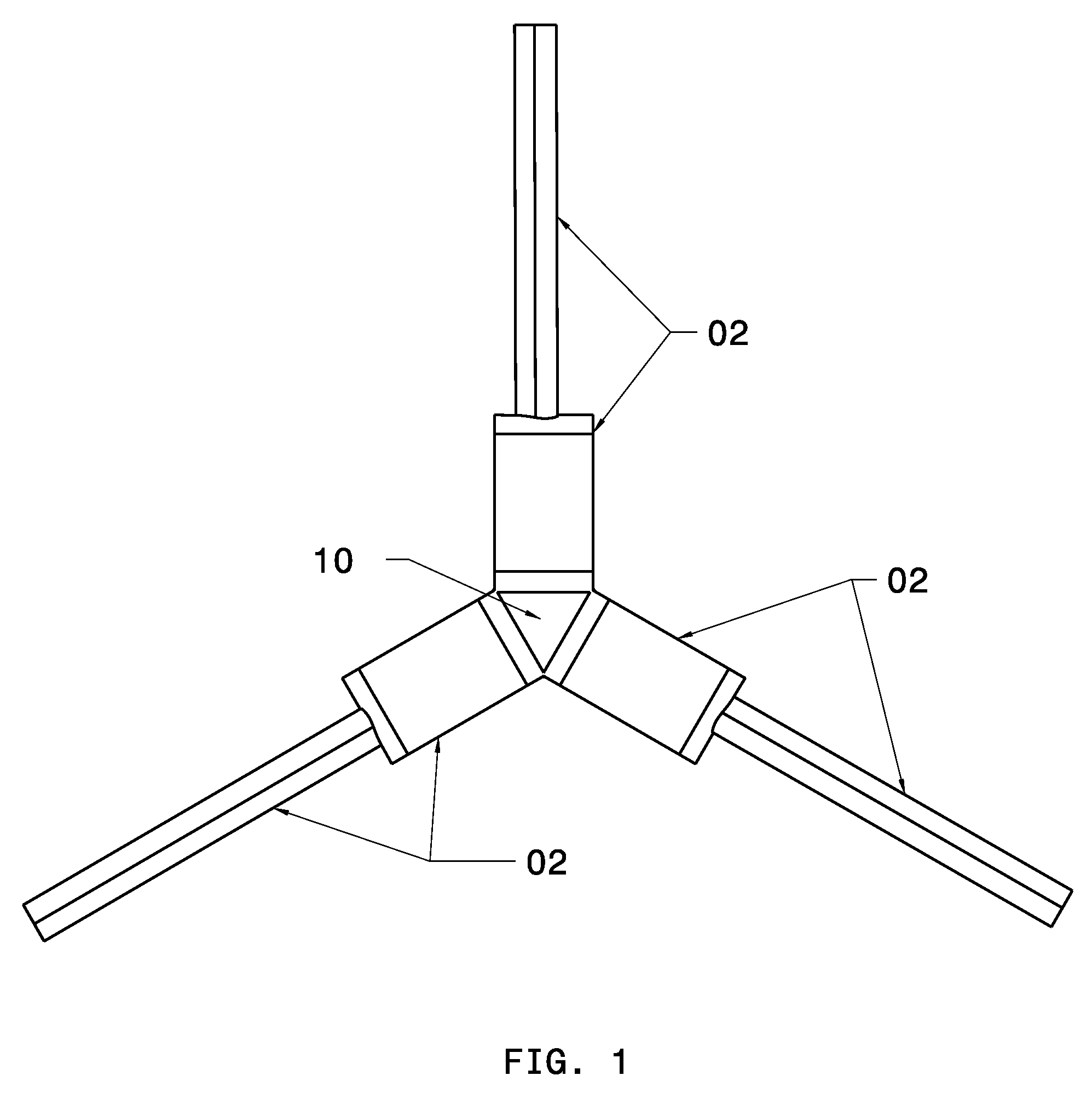
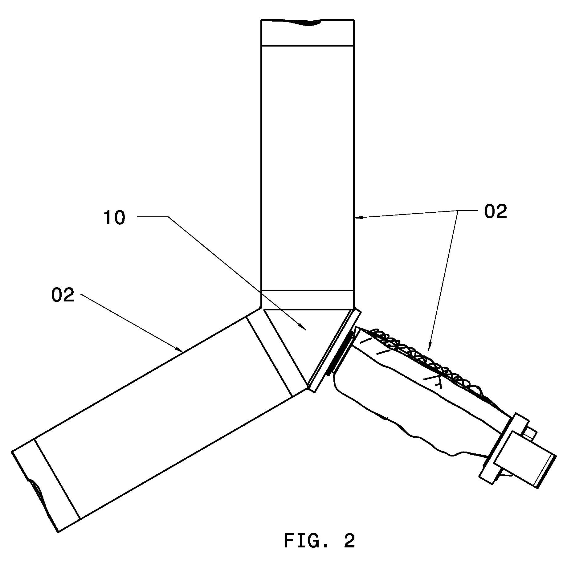
[0059]Referring to FIG. 1 and FIG. 2 the retractable composite impeller assembly embodiment comprising of two, three, or plurality of rotor blades 02 is depicted. FIG. 1 also shows the retractable composite rotor assembly of a first preferred embodiment comprising of the major subassemblies and in its fully extended condition. The geometry of rotor hub 10 corresponds to the plurality of rotor blades 02. In this configuration each rotor blade assembly 02 experiences the same centripetal force during rotation and deceleration.

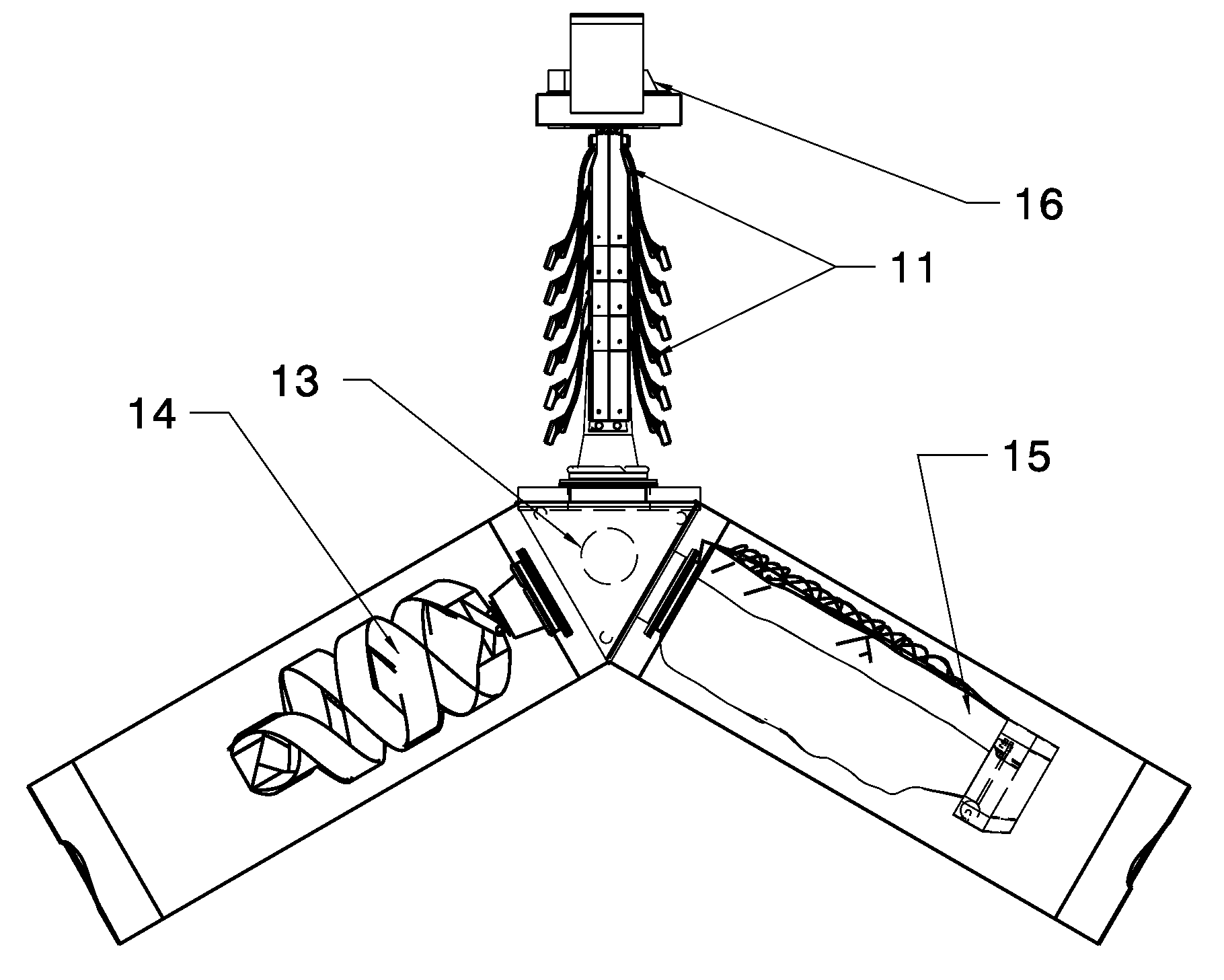
[0060]Referring to FIG. 1 thru FIG. 4, the major subassemblies which are comprising the present invention work in concert to allow the rotor blade 02 to have the ability to become extended when the system is rotated, and contracted when the system is forced to come to rest and in a controlled manner by way of a retracting reel assembly 13. The primary subassembl...


PUM


Abstract

An extendable / retractable rotor for vertical lift has plural rotor blades, each with a rotor hub assembly, blade top and bottom hinged casings and a pitch disc rotateable about its longitudinal axis to change the rotor blade pitch angle. An interlink assembly has a blade base, a link base subassembly of top and bottom link hubs, two locking arms, a retracting reel assembly having exterior and interior rotor axles, a breaking actuator having plural outer breaking notches, plural recoiling spools forming a reel cage and a locking mechanism preventing blade retraction. A helical ribbon assembly with plural sequentially overlapped ribbons has pin restraints, plural layers each helically wound around the interlink assembly and a flexible and elastic sleeve of plural elastic ribs. An elastic and flexible skin made of composite elastomeric sheet reinforced by fibers is provided as is a zipper slider mechanism of a main slider, a zipper wedge, a wedge track, plural spring loaded wheels, plural hinged plates and plural hinge joints.

Description

CROSS-REFERENCE TO RELATED APPLICATIONS[0001]This application claims priority on U.S. Provisional Patent Application No. 61 / 108,282, filed Oct. 24, 2008, which is also incorporated here by reference.BACKGROUND OF THE INVENTION[0002]1. Field of the Invention[0003]The present invention relates primarily to the field of aerospace and the field of lift generating structures. More specifically the invention relates to the design of retractable rotor blades. Even more specifically the present invention relates to the design of retractable rotor blades used as means to produce lift and thrust for vertical and short take off vehicles.[0004]2. Description of the Related Art[0005]Rotor blades have been used for many years to achieve flight. A short coming of related art is that conventional rotor blades and rotor blade assemblies have longitudinally rigid structure (U.S. Pat. No. 7,475,847). Many rotor blades are now made of carbon fiber, fiber glass and other composite materials. These conve...

Claims


Application Information

Patent Timeline
Patent Type & Authority Applications(United States)
IPC IPC(8): B64C11/28
CPCB64C27/46B64C11/28B64C2027/4736B64C27/50B64C27/473B64C27/51F05D2250/90
Inventor CARABALLOSO, ESTEBAN A
Owner CARABALLOSO ESTEBAN A
Learn More