Vertical Take-Off and Landing Unmanned Aerial Vehicle Having Foldable Fixed Wing and Based on Twin-Ducted Fan Power System

a technology of fixed wing and power system, which is applied in the field of vertical take-off and landing unmanned aerial vehicles with foldable fixed wing and based on twin-ducted fan power system, can solve the problems of difficult to achieve stable aerodynamic effects of tilting airfoils, large number of accidents and even frequent crashes in the practical process, and low utilization of rotating mechanism, so as to improve the aerodynamic performance of the fan, reduce the power loss of the fan blade tip, and improve the lift-to-

Active Publication Date: 2022-03-17
SOUTH CHINA UNIV OF TECH
View PDF0 Cites 3 Cited by
  • Summary
  • Abstract
  • Description
  • Claims
  • Application Information

AI Technical Summary

Benefits of technology

[0022]1. A ducted fan is employed as a power system in the present invention, which is advantageous in: the aerodynamic performance of the fan is optimized by the external contour of duct, the formation of vortex at a fan blade tip is blocked by a duct wall to reduce the power loss of the fan blade tip, and at the same time the duct itself can generate lift under the suction of the fan. Therefore, compared with an isolated propeller, a ducted fan of the same radius has a higher lift-to-weight ratio (generally about 27% higher) at the same energy consumption. At the same time, the duct can generate part of the lift (about 10% of wing lift) during horizontal flight of the aerial vehicle. Therefore, employing the ducted fan as the power system of the vertical take-off and landing aerial vehicle can improve the efficiency in take-off and landing, hovering and flight of the aerial vehicle and effectively reduce the energy consumption; a single ducted fan power source satisfies the multi-mode lift / thrust requirements, has high efficiency, and is suitable for vertical take-off and landing / long-range flight; and at the same time, the ducted fan system has low aerodynamic noise, high safety and high reliability.
[0023]2. The ducted attitude control servo plane is arranged in a stable, high-speed slip flow in the duct, reducing external aerodynamic operating surfaces (tails, etc.), and avoiding the instability of low-speed (take-off and landing) aerodynamic disturbance failure from conventional designs and the gust disturbance of large-size exposed propellers; and the ducted power configuration does not require a tilting mechanism, such that the system reliability is improved, and at the same time, the shape is simple to effectively reduce the radar reflection area.
[0024]3. The tail-propulsion power arrangement guarantees the nose not affected by propellers, and can facilitate the installation of various sensors and communication devices; and the tail-propulsion ducted fan can obtain the maximum arm of force for attitude (pitch, roll) control, and can improve its anti-disturbance capacity to the utmost extent.
[0025]4. The invention employs a specific duct-wing relative position to enable the combined optimization. The ducted fan power system is located below the trailing edge of the wing, and the Coanda effect is created near the wing under the suction of the ducted fan, thereby effectively improving the adverse pressure gradient on an upper surface of the wing and slowing down the separation of airflow at a boundary layer of the wing, such that the aerodynamic performance of the wing is greatly enhanced. Compared with a traditional fixed-wing structure, the lift coefficient of the wing increases by 25%, the stall angle of attack increases to 40°, and the overall lift-to-drag ratio increases by 15%. This technology improves the stability and safety of the switching process. Therefore, the aerial vehicle of the present invention can further reduce the power loss during the take-off and landing and extend the flight time, and can perform short-distance, ground-sliding take-off and landing under extreme conditions that are not suitable for the vertical take-off and landing.
[0026]5. The foldable wing is stowed during the vertical take-off and landing, which can decrease the frontal area of the wing exposure to crosswind to enhance the anti-wind capability of the aerial vehicle, and the wing is expanded during the horizontal flight, which can obtain large lift.
[0027]6. The ducted fan is affected by crosswind during operation to generate momentum resistance at the plane of the duct entrance, and the resistance is the primary resistance during the low-speed flight of the aerial vehicle. Since the center of gravity of the aerial vehicle is positioned relatively forward (at a higher position when vertically placed), and the ducted fan and its control servo plane are positioned relatively backward (at a lower position when vertically placed), the whole aerial vehicle generates a low head moment to the gravity by the crosswind resistance during the vertical take-off and landing and the hovering. Therefore, in a strong crosswind environment, the aerial vehicle can automatically reach a stable state with a small inclination against the wind. This mechanism of action enables the aerial vehicle of the present invention to greatly improve its anti-disturbance capability during the vertical take-off and landing. In addition, the landing angle of the aerial vehicle can be adjusted by means of the retractable landing gear, to cooperate with the aerial vehicle to achieve tilted anti-wind take-off and landing and further improve its stability.

Problems solved by technology

However, a complicated rotation mechanism design is required for a tilting mechanism, its structure is often damaged resulting from adverse factors, such as under a gyro alternating moment generated by a powered rotating propeller / wing, and it is difficult to achieve stable aerodynamic effects on tilting airfoils at a low speed and during transition.
At present, a large number of accidents and even frequent crashes occur in the practical process (reports of V-22 Osprey crashes sometimes occur).
Moreover, the rotating mechanism has low utilization and becomes an unnecessary load during cruising flight, affecting the overall flight performance.
For a fixed-wing aerial vehicle with an auxiliary vertical lift system, two power systems thereof are separately activated in a vertical take-off and landing mode and a horizontal flight mode, which causes the low efficiency of the whole power device so as to affect the operational performance, such as flight time / distance / maneuverability, of the aerial vehicle, and in addition, the exposed rotor also has a large aerodynamic resistance during horizontal flight, such that it is difficult to achieve high-speed cruising flight.
The disadvantage thereof is in that the flight state transition process is difficult to control and is greatly affected by wind.
In addition, its power system needs to achieve an overall thrust-to-weight ratio of at least 1 or more, such that the disc radius is large, the speed of rotation is high, the aerodynamic resistance is high during the horizontal flight, and it is difficult to achieve a high cruising speed.
Moreover, the flying wing structure has a large frontal area during the vertical take-off and landing and the transition, and is greatly affected by gusts.
Most of the existing vertical take-off and landing aerial vehicle configurations are affected by unstable airflow due to the small aerodynamic effect on operating airfoils during the take-off and landing, and a large-size rotary wing exposed outside is also affected by gusts (in addition, the installation of a nose often affects the electronic cabin communication and sensing devices); and the tilting power mechanism is complicated and vulnerable, has poor stability, has low auxiliary redundant power efficiency, and is not suitable for a large-load, long-range design.

Method used


Image

  • Vertical Take-Off and Landing Unmanned Aerial Vehicle Having Foldable Fixed Wing and Based on Twin-Ducted Fan Power System
  • Vertical Take-Off and Landing Unmanned Aerial Vehicle Having Foldable Fixed Wing and Based on Twin-Ducted Fan Power System
  • Vertical Take-Off and Landing Unmanned Aerial Vehicle Having Foldable Fixed Wing and Based on Twin-Ducted Fan Power System

Examples


embodiments

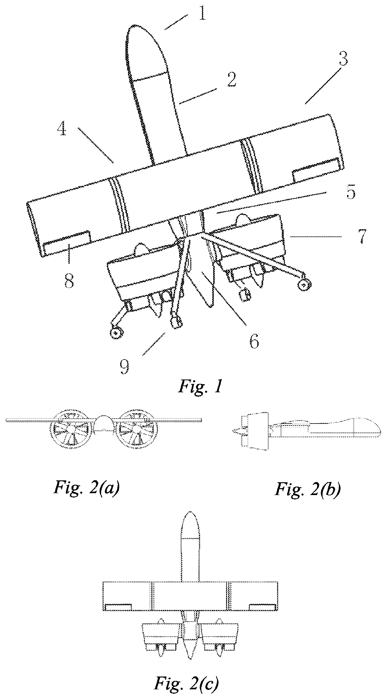
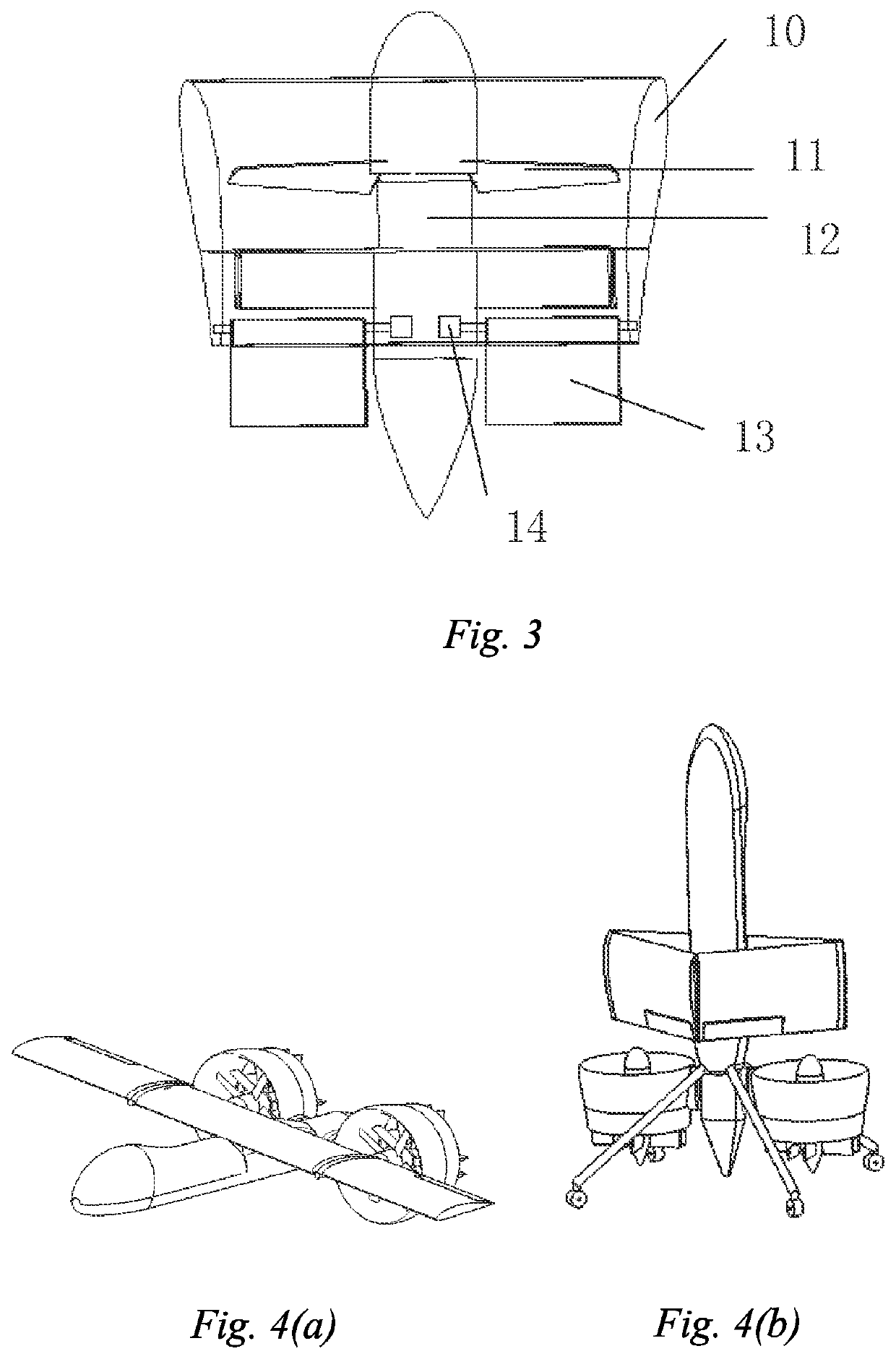
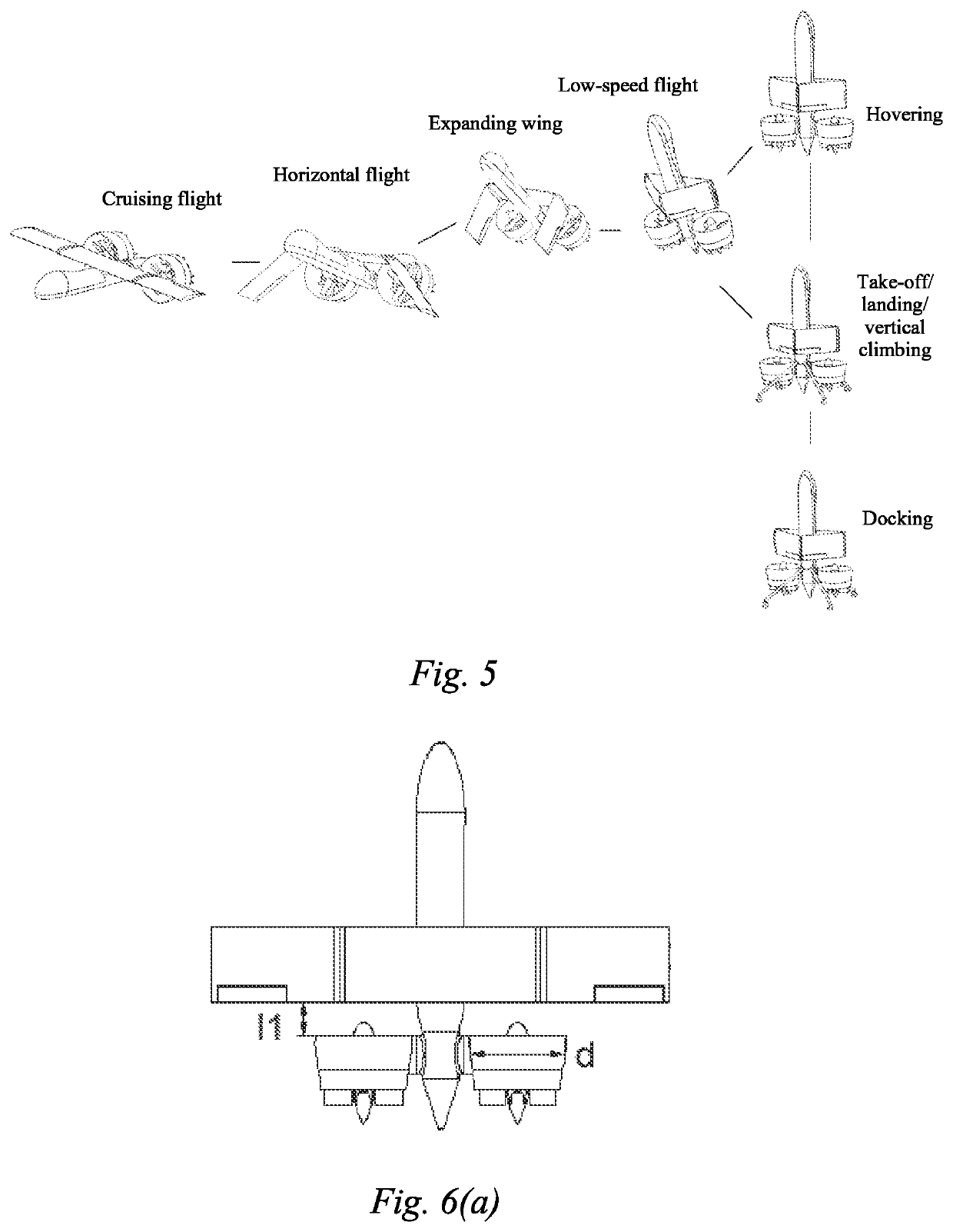
[0045]A three-dimensional schematic view of various main components of an aerial vehicle of this embodiment is as shown in FIG. 1, the aerial vehicle comprising: a fuselage, a foldable wing 3, ducted fan power systems 7 and a retractable landing gear 9, the fuselage being divided into a nose 1, a front fuselage 2, a middle fuselage 5 and a rear fuselage 6, wherein the ducted fan power systems 7 are symmetrically distributed on both sides of the rear fuselage 6 in a transverse arrangement, the foldable wing 3 is arranged at the front of the middle fuselage 5 in an upper single-wing arrangement, the retractable landing gear 9 is arranged at the front of the rear fuselage 6, the aerial vehicle is in a tailless arrangement, the center of gravity of the aerial vehicle is located at the rear of the front fuselage 2, and ducts and the wing are combined in an optimized manner by means of a specific position relationship therebetween.

[0046]In this embodiment, an aerodynamic arrangement emplo...


PUM


Abstract

A vertical take-off and landing (VTOL) unmanned aerial vehicle having a foldable fixed wing and a twin-ducted fan power system (7) arranged at a tail portion of a fuselage in a transverse and tail propulsion arrangement provides lift for vertical take-off and landing and propulsion for horizontal flight. By means of deflection of a control servo plane arranged at a duct exit, a vectored thrust is provided to enable a fast attitude change. When the aerial vehicle takes off and lands vertically / flies at a low speed, the wing is folded to reduce the frontal area exposure to crosswind. When the aerial vehicle is flying horizontally, the wing is expanded to obtain larger lift. A Coanda effect is created at a trailing edge of the wing by suction of the duct to improve performance.

Description

CROSS-REFERENCE TO RELATED APPLICATIONS[0001]This application is the United States national phase of International Application No. PCT / CN2017 / 111341 filed Nov. 16, 2017, and claims priority to Chinese Patent Application No. 201710343539.0 filed May 16, 2017, the disclosures of which are hereby incorporated by reference in their entirety.TECHNICAL FIELD[0002]The present invention relates to the technical field of aerial vehicles, and in particular to a vertical take-off and landing unmanned aerial vehicle having a foldable fixed wing and based on a twin-ducted fan power system.BACKGROUND ART[0003]Vertical take-off and landing aerial vehicles have always been a hot spot in the aeronautical engineering research. In recent years, due to the advance in materials, energy sources, power and control technology, many advanced solutions have been applied to the vertical take-off and landing aerial vehicles. At present, the several types of designs enabling a shipborne vertical take-off and la...

Claims


Application Information

Patent Timeline
Patent Type & Authority Applications(United States)
IPC IPC(8): B64C39/02B64C29/02B64C1/06B64C11/00B64C3/54B64C25/18B64C9/00B64C13/24
CPCB64C39/024B64C29/02B64C1/068B64C11/001B64C3/546B64C2201/162B64C9/00B64C13/24B64C2201/021B64C2201/102B64C25/18B64C1/00B64C3/56B64C29/0025B64U10/25B64U30/20B64U50/14B64C39/068Y02T50/10B64U30/12B64U50/19
Inventor PEI, HAILONGCHENG, ZIHUAN
Owner SOUTH CHINA UNIV OF TECH
Why Eureka
Try Eureka