Piling fender

a fender and fender technology, applied in the field of fender, can solve the problems of tearing the fender material away from the fastener, irregular contours of the piling, and the fender material of the piling is easily damaged and unsightly,

Inactive Publication Date: 2004-02-03
PAWLING ENGINEERED PROD
View PDF24 Cites 26 Cited by
  • Summary
  • Abstract
  • Description
  • Claims
  • Application Information

AI Technical Summary

Benefits of technology

The arrangement of the invention, as described above, provides for a neat, clean and uniform appearance of the marina pilings. The fastening devices, used for securing the retaining channels to the pilings are both concealed and protected by the overlying fender elements. Additionally, the rigid retaining channels extend straight down the piling elements, bridging over any gouged areas of the piling, providing neat appearing, straight edges and providing support and refinforcing for the fender in the gouged areas.

Problems solved by technology

Piling fenders of the type indicated above tend to become quickly damaged and unsightly, as a result of contact with vessels moving either forwardly or rearwardly at the time of contact.
Particularly in the case of wooden pilings, the contours of such pilings frequently are irregular, either naturally or because of damage resulting from contact with vessels.
Thus, piling fenders frequently are not fully supported underneath, and are therefore prone to lateral distortion, which can in some cases tear the fasteners out of the piling and in other cases tear the fender material away from the fasteners.
Among other things, standard piling fenders when partially detached from a piling, are very unsightly and give the appearance of a poorly kept marina.
This not only gives the entire installation a somewhat unsightly appearance, but it also makes the fender more easily prone to damage and distortion because the fender edge can easily be snagged in areas between fasteners, by a vessel moving forwardly or rearwardly at the moment of contact.

Method used


Image

  • Piling fender
  • Piling fender
  • Piling fender

Examples


Embodiment Construction

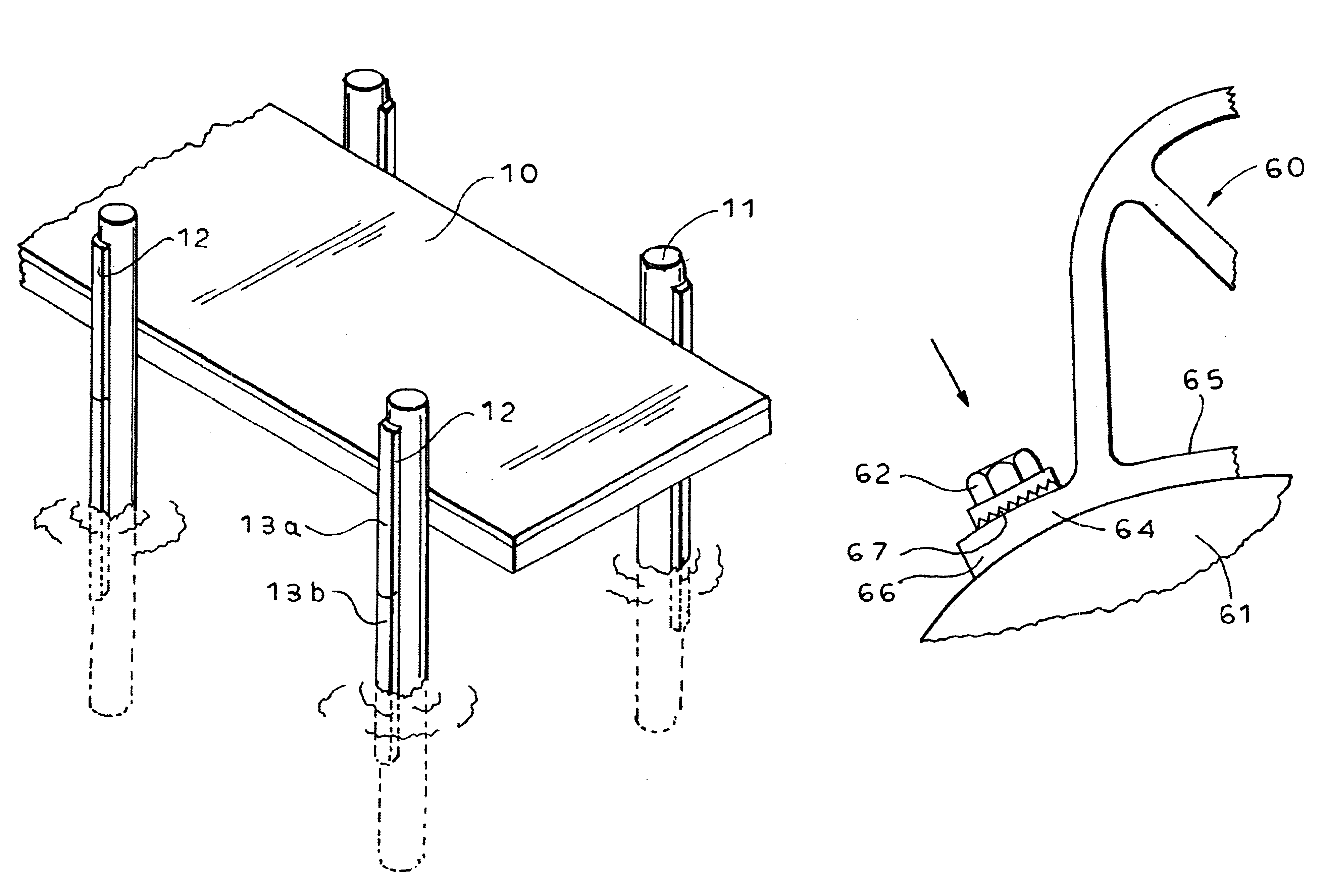
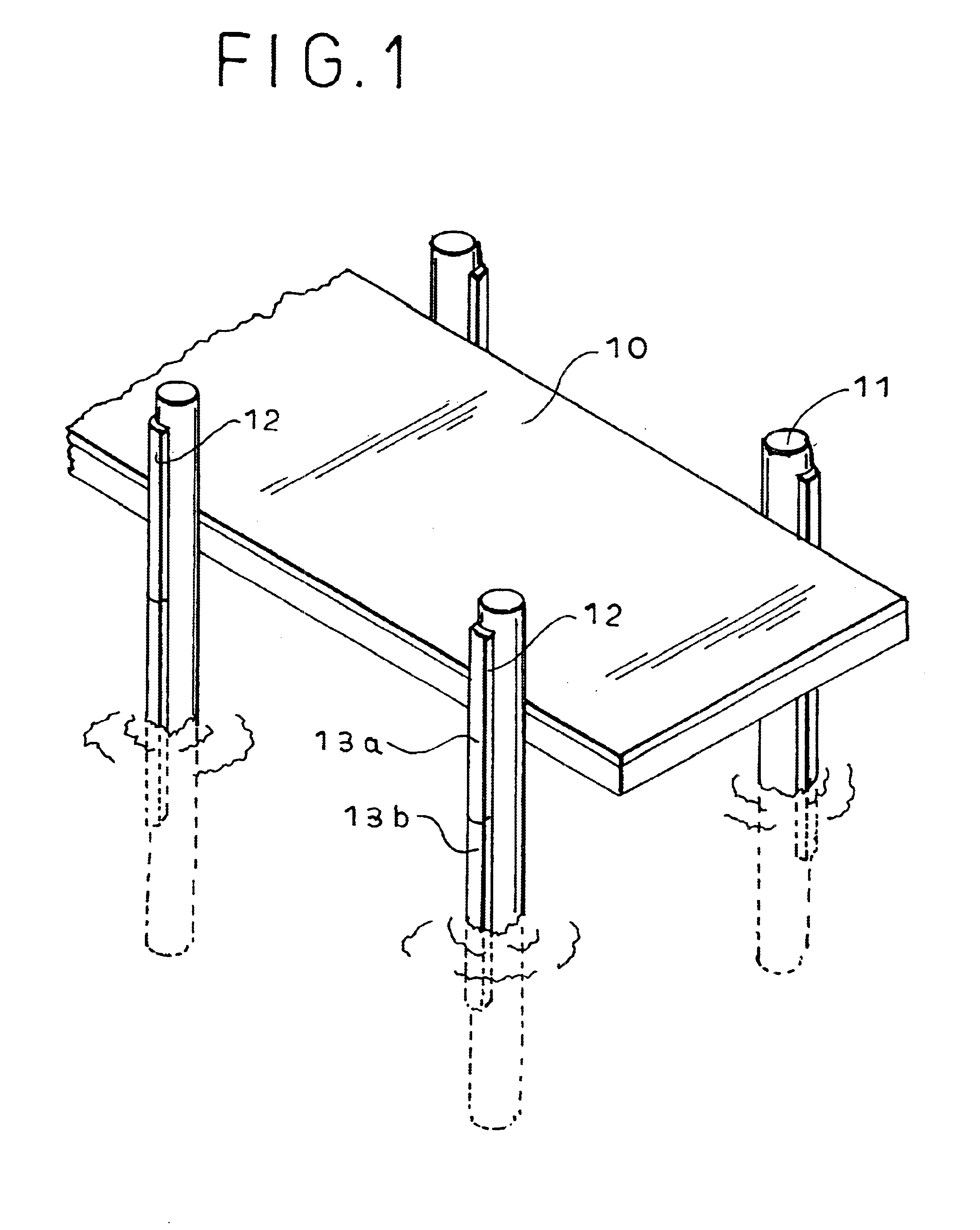
Referring now to the drawings, FIG. 1 represents a typical form of fixed dock structure, in which a dock platform 10 is supported on opposite sides by multiple vertical pilings 11 driven into the seabed. The platform 10 is rigidly secured to the pilings by suitable means, such as bolts (not shown).

Vessels approaching and / or tied up at the dock have to be concerned about avoiding direct contact between the topsides of the vessel and the outer surfaces of the pilings 11, to prevent damaging the vessel. The vessel can (and sometimes does) provide its own fendering. However, many marinas provide vertical fendering along the outside faces of the pilings, as indicated generally at 12 in FIG. 1. Such fendering extends over a sufficient vertical portion of the pilings 11 to provide protection for vessels of various sizes at various stages of tide. Because of the rather severe duty to which the piling fenders are subjected in resisting contact by heavy vessels, and because the somewhat harsh...


PUM


Abstract

A dock fender, particularly for attachment to the outer face of a dock piling for cushioning vessels attached to the dock. The fender is of extruded construction, having laterally extending flanges which are conformable to the surface of the pilings. The fender is attached to the piling by lag screws applied to the flanges. Special washers, of rectangular configuration, are provided to underlie the heads of the lag screws. The washers are formed with anti-rotation means such that, after initial proper alignment of the washers with the fender flanges, the washers will retain such orientation during rotational tightening of the lag screws. In one form, the anti-rotation means comprises bent corners of individual washers. In another form, the washers are of a length to engage more than one lag screw.

Description

Piling fenders are commonly used in connection with fixed docks supported by vertical pilings driven into the seabed. To avoid damaging the top sides of vessels approaching and tied to the dock, resilient fender elements commonly are secured to the outer surfaces of the piling, extending vertically along the piling over the region thereof expected to be contacted by vessels of various sizes and at various stages of the tides in tidal waters. One common type of dock piling is round wooden piling which is driven deep into the seabed, leaving a portion exposed above the water level for securing and supporting the dock. Various forms of resilient devices are secured to outer surfaces of such pilings, using nails, lag screws or the like. An example of such is shown in the Matthews U.S. Pat. No. 3,950,953.Piling fenders of the type indicated above tend to become quickly damaged and unsightly, as a result of contact with vessels moving either forwardly or rearwardly at the time of contact....

Claims


Application Information

Patent Timeline
IPC IPC(8): E02B3/26E02B3/20
CPCE02B3/26Y02A30/30
Inventor BUSBY, ROBERT B.
Owner PAWLING ENGINEERED PROD
Why Eureka
Try Eureka