Common rafter and hip layout tool

a technology of hip and rafter, which is applied in the field of common rafter and hip layout tools, can solve the problems of single device not providing marking of physical relationship measuring device not providing marking

Inactive Publication Date: 2004-02-24
NYQUIST SHELBY M
View PDF27 Cites 30 Cited by
  • Summary
  • Abstract
  • Description
  • Claims
  • Application Information

AI Technical Summary

Benefits of technology

It is a yet further object of this invention to provide a device which provides for marking of the physical relationship between the tail cut and the seat cut and, therefore, do not require a separate measurement be taken before marking of the seat cut.
It is a yet further object of this invention to provide a device which provides for ease of use in that multiple manual adjustments do not have to be made by the user in order to maintain the angular relationship of the rafter ridge cut and the seat cut.

Problems solved by technology

The single device does not provide for marking of the physical relationship between the tail cut and the seat cut, and thus requires a separate measurement be taken.
The collapsible rafter square does not provide for marking of the physical relationship between the tail cut and the seat cut, and thus requires a separate measurement be taken.
The measuring device does not provide for marking of the physical relationship between the tail cut and the seat cut, and thus requires a separate measurement be taken.
U.S. Pat. No. 6,293,028 discloses a construction tool which is useful for the marking of locations for the roof ridge cut, seat cut, and tail cut; however, no provision is made for setting the angle of such cuts.
Accordingly, it can be seen that the prior art provides less than ideal solutions for the problem commonly encountered by carpenters and craftsmen in laying out and marking common roof rafters for the roof ridge cut, seat cut, and tail cuts.
A first problem encountered in the prior art is that some prior art devices do not provide for the marking of the seat cut.
A further problem encountered in the prior art is that some prior art devices do not provide for marking of the physical relationship between the tail cut and the seat cut and, therefore, require a separate measurement be taken.
A yet further problem encountered in the prior art is that some prior art devices do not provide for ease of use in that multiple manual adjustments have to be made by the user in order to maintain the angular relationship of the rafter ridge cut and the seat cut.
A yet further and final problem encountered in the prior art is that some prior art devices by their design for general applicability to uses in the construction trades do not specifically and clearly indicate their use in laying out the common cuts to be marked and made for a common roof rafter.

Method used


Image

  • Common rafter and hip layout tool
  • Common rafter and hip layout tool
  • Common rafter and hip layout tool

Examples


Embodiment Construction

)

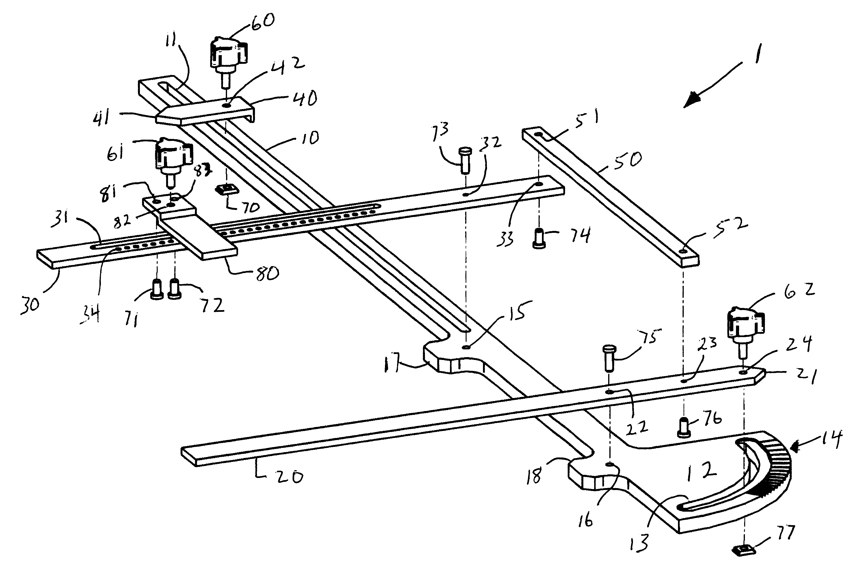
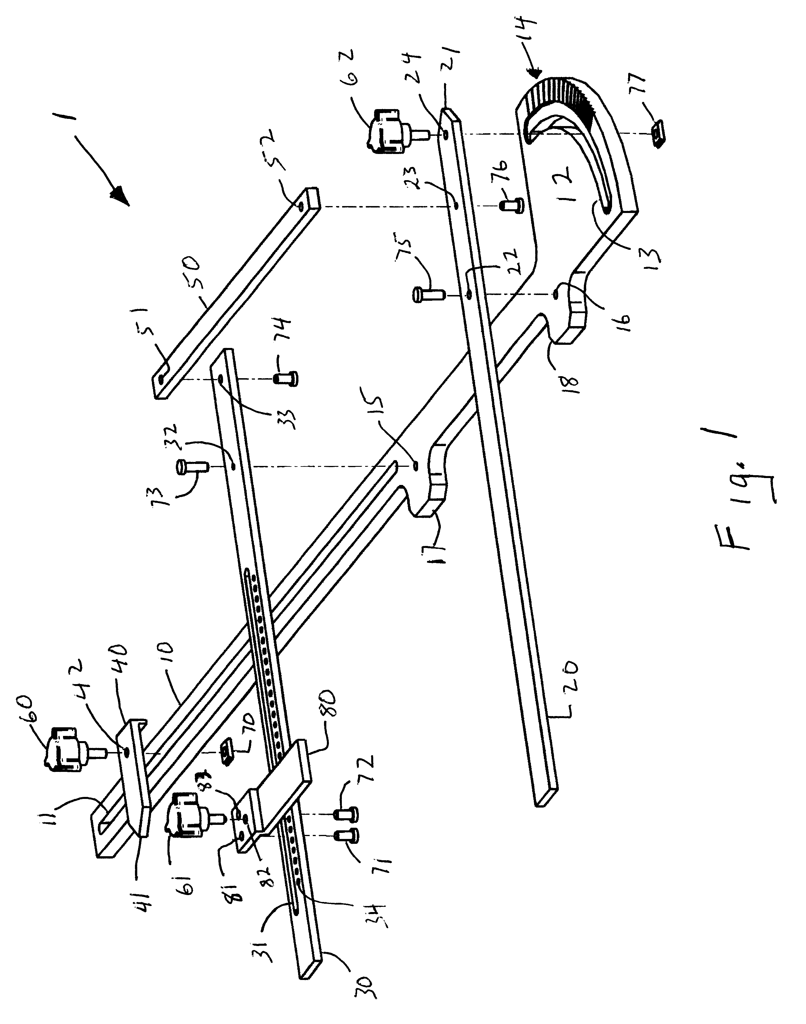
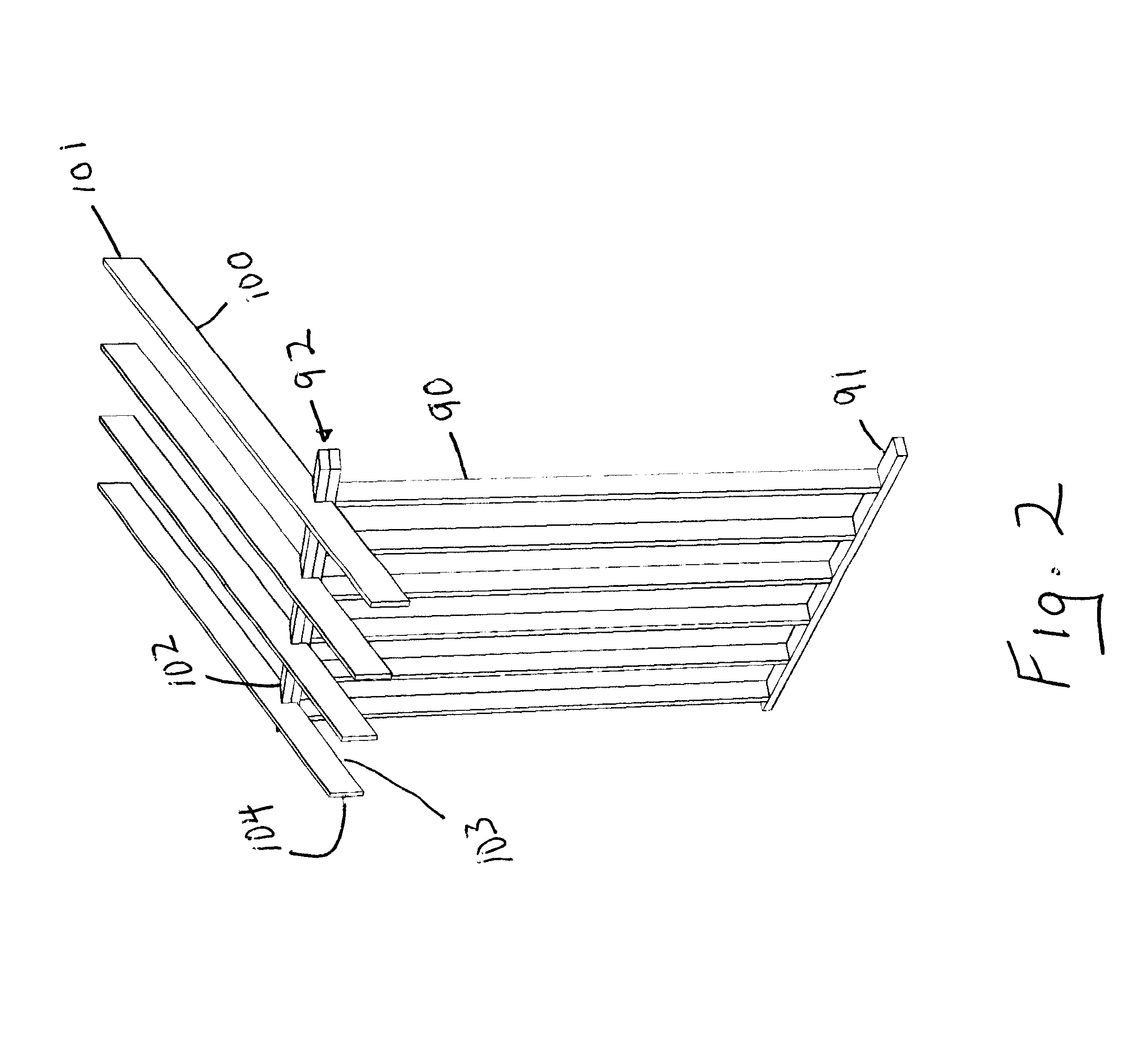
As seen by reference to FIGS. 1 and 2, the instant invention is of a common rafter and hip layout tool 1, useful in marking the common cuts to be made in a roof rafter 100. The common cuts to be made in a roof rafter 100 are, at the uppermost end of the roof rafter 100, the common ridge cut 101; at the lowermost end of the roof rafter 100, the tail end cut 104, and at the point between the common ridge cut 101 and the tail end cut 104 where the common roof rafter 100 will cross over or lie upon the top member of the frame 92 of the vertical wall of the structure being roofed, the bird's mouth cut or seat cut 102.

The common rafter and hip layout tool 1 of the instant invention is, in major division, comprised of a main body 10, a common cut marking edge 20, a bird's mouth marking arm 30, a tail length marking arm 40, a synchronizing bar 50, and a seat cut marking arm 80.

The main body 10 is an elongated bar with a slot 11 cut approximately mid-width and running longitudinally the len...


PUM


Abstract

A common rafter and hip layout tool which provides a protractor portion, a common cut marking edge, a common cut marking edge pantograph arm to which is connected a bird's mouth marking arm, a seat cut marking arm connected at a right angle to the bird's mouth marking arm and a tail length marking arm. The pantograph arm and connected bird's mouth marking arm facilitates the marking of the bird's mouth cut and the seat cut. Movement of the common cut marking edge to the location indicated by the tail length marking arm facilitates the making of parallel cuts for the common rafter ridge cut and the tail cut.

Description

a. Field of the InventionThe present invention is related generally to the field of devices and tools useful in marking roof rafters for cutting to shape for installation.More particularly the present invention is related to devices and tools useful in marking roof rafters for cutting to shape for installation that provide for the marking of the common cuts to be made in a roof rafter, the common ridge cut, the bird's mouth or seat cut, and the tail end cut.Yet more particularly, the present invention is related to devices and tools that provide for marking of the physical relationship between the tail cut and the seat cut and, therefore, do not require a separate measurement be taken before marking of the seat cut.Yet more particularly, the present invention is related to devices and tools that provide for ease of use in that multiple manual adjustments do not have to be made by the user in order to maintain the angular relationship of the rafter ridge cut and the seat cut.In a yet...

Claims


Application Information

Patent Timeline
Patent Type & Authority Patents(United States)
IPC IPC(8): B43L7/00B43L7/10
CPCB43L7/10
Inventor NYQUIST, SHELBY M.
Owner NYQUIST SHELBY M
Why Eureka
Try Eureka