Rock stabilizing apparatus and method

a technology of rock stabilizing apparatus and rock formation, which is applied in the direction of screws, nuts, bolts, etc., can solve the problems of increasing the cost of the overall system, difficult to use in underground mining operations, and devices that are not well suited to applications, so as to eliminate safety hazards, easy and inexpensive manufacturing

Inactive Publication Date: 2004-03-02
DYWIDAG SYST INT CANADA
View PDF7 Cites 24 Cited by
  • Summary
  • Abstract
  • Description
  • Claims
  • Application Information

AI Technical Summary

Benefits of technology

Yet another object of the present invention is to provide a rock stabilizing apparatus and method for anchoring unstable rock formations adapted for applications where adhesion materials are used to fix the reinforcing member within the borehole.
The objects of the present invention are satisfied through the provision of a rock stabilizing apparatus and method for anchoring unstable rock formations adapted for use with adhesion material. The apparatus comprises an elongated reinforcing member having a threaded portion at a bottom end; and, a top end adapted to be embedded permanently within a hardenable adhesion material within the drilled hole. The threaded bottom portion and the top end are at opposite ends of the same member. The reinforcing end is inserted into a drilled hole through the unstable rock formation into stable rock. The drilled hole is sufficiently deep so that when the member is entirely inserted into the drilled hole the threaded end is partially inserted into the drilled hole. There is at least one bearing plate member retained on the threaded bolt portion of the reinforcing member. The threaded portion has a top end and a bottom end, and can be rotated through the centre of the plate. The plate can be advanced so that it abuts against the rock face for transmitting compressive forces to the rock face. There is at least one nut threadably advanceable over the threaded portion. The nut acts to advance the bearing plate to the rock face and applies a tensioning force into the reinforcing member when it is tightened against the bearing plate. A shearing element is provided within the nut that shearably fixes the nut to a predetermined and variable position on the threaded portion of the reinforcing member. The nut has a first temporary pre-torgue.sub.max operating position wherein it is fixed to the member-threaded portion at its bottom end by the shearing element thus permitting the nut and member to be rotated as one. The first temporary pre-torque.sub.max operation position is adopted when it is necessary to mix adhesion material within the borehole for curing. The nut has a second post-torque.sub.max permanent operation position that is adopted once the shearing element has sheared at torque.sub.shear and the nut is free to advance along the threaded portion of the reinforcing member. This second post-torque.sub.max operating position is adopted when it is necessary to abut the bearing plate against the rock formation and then further torque the nut to torque.sub.max thus adding compressive forces to the rock formation through the bearing plate and also adding tensile forces to the reinforcing member anchored within the drilled hole. The shearing element is adapted to shear at torque.sub.shear when a predetermined amount of torque is applied to the nut. Torque.sub.shear occurs at a predeterminable torque that is made dependent upon the curing properties of the adhesion material. The breakage of the shearing element at torque.sub.shear will not damage the threads on the member. Additionally, the remnants of the shearing element, once sheared, are retained within their respective bores to eliminate safety hazards that may result from energized pieces of the shearing element acting as projectiles.

Problems solved by technology

This device is not well suited to applications where the reinforcing rod is used to mix adhesion materials during curing because there is disclosed no way to rotate the rod within the hole.
It relies upon a plurality of parts making it difficult to use in underground mining operations.
It relies upon on a relatively complex coupling device that that will be expensive to manufacture and therefore adds expense to the cost of the overall system.
The reliance upon a coupling between the bolting rod and the reinforcing rod creates a weak link that may fail during rotation necessitating the entire system and adhesion material to be removed from the hole.

Method used


Image

  • Rock stabilizing apparatus and method
  • Rock stabilizing apparatus and method
  • Rock stabilizing apparatus and method

Examples


Embodiment Construction

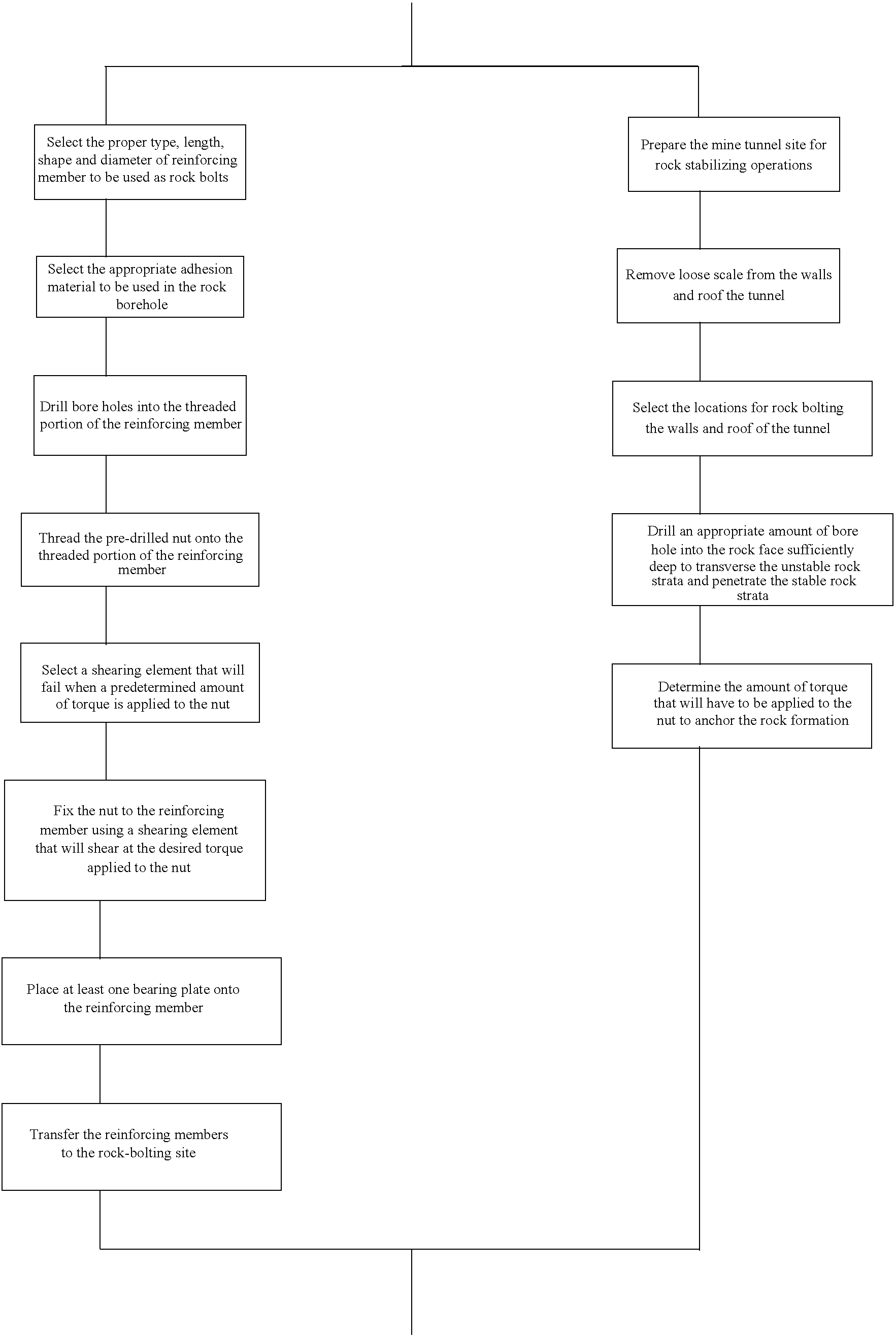
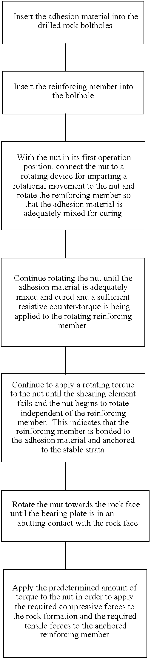
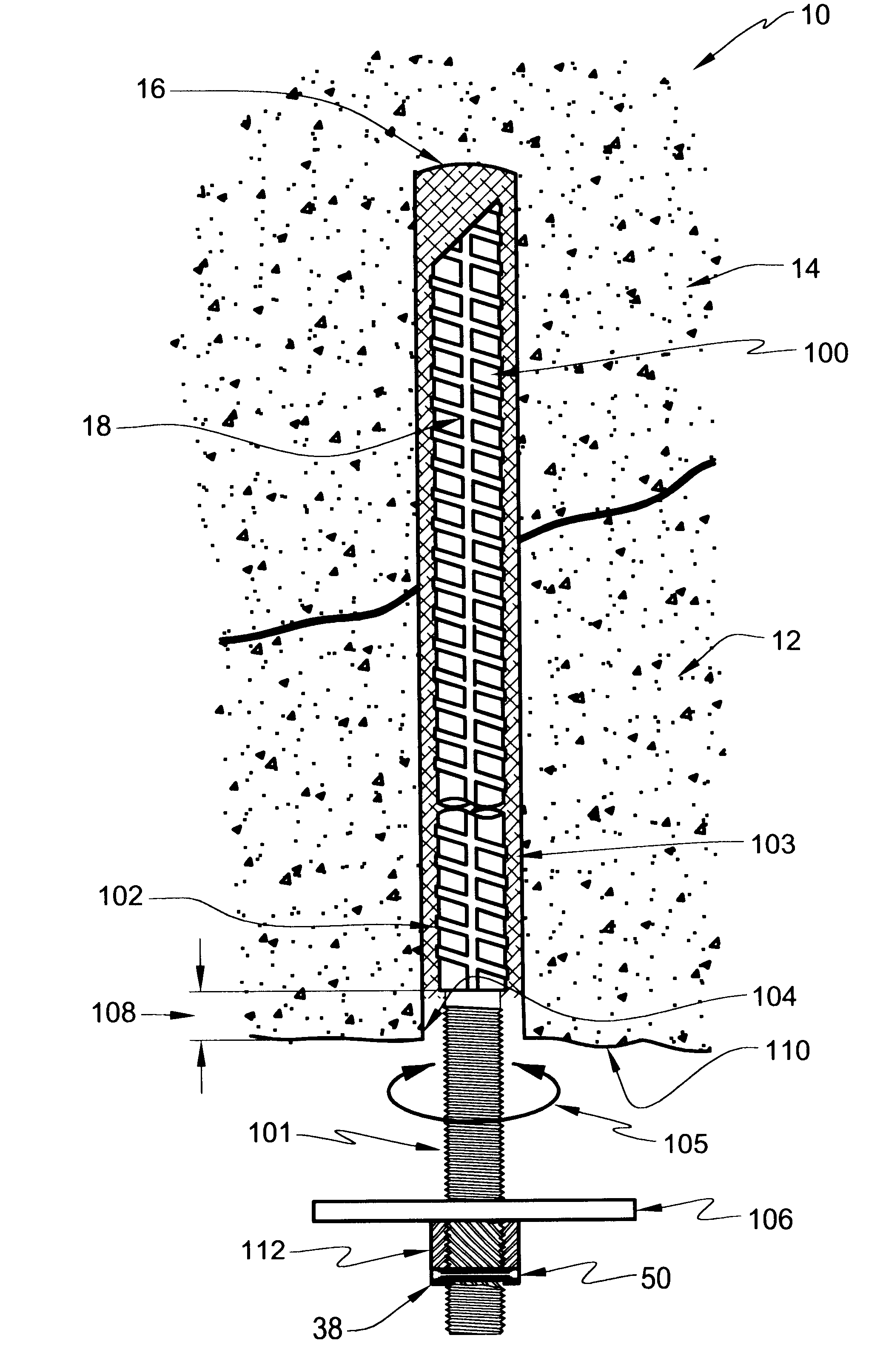
Referring to FIG. 1 there is shown a rock stabilizing apparatus for anchoring unstable rock formations (12) to stable rock formations (14) in mining operations of a preferred embodiment of the invention generally designated as (10). The apparatus is shown in its pre-torque.sub.max and pre-torque.sub.shear states. The apparatus is adapted to be inserted into a pre-drilled hole (16) that extends through the unstable portion (12) to a stable portion (14) of the rock formation as might be found in the roof or wall of a mine tunnel. The apparatus comprises a tensionable member (18). In a preferred embodiment of the invention the member is a reinforcing member generally tubular in shape having a top ribbed portion (100) and a bottom threaded portion (101). In alternative embodiments of the invention the reinforcing member may comprise one of a steel bar, a cone bolt, a standard rock bolt, or a reinforcing cable. The portion inserted into the drilled hole may be smooth or textured to promo...


PUM


Abstract

A rock stabilizing apparatus and method for use with adhesion materials has a tensionable reinforcing member having a threaded portion at one end and an opposite end. The member-threaded portion threadably receives a nut and a bearing plate is retained on the member-threaded portion by the nut. A shearing element is provided for temporarily fixing the nut in a first operating position. At a predetermined torque, the shearing element fails and the nut is freed to advance on the threaded member portion from the first temporary operating position to a second permanent operating position. The first fixed operating position is located at the top end of the member-threaded portion. The second operation position is located at the bottom end of the member-threaded portion so that the bearing plate is in abutting contact with the face of the rock formation. In its first operating position the nut and reinforcing member may be rotated together for mixing the adhesion materials located within the drill hole.

Description

BACK GROUND OF THE INVENTION1. Field of the InventionThis invention relates to a rock stabilizing apparatus and method for anchoring unstable rock formations in underground mines and more particularly relates to an apparatus and method using a tension member that is embedded into a hardenable adhesion material for creating stabilizing forces within an unstable rock formation.2. Background of the InventionIn underground mines it is important to secure the roof and walls of a tunnel against collapse of unstable rock formations that will hang from stable rock formations. Such situations may be caused by having to tunnel through naturally fractured rock formations or by blasting operations within the mine. Scaling the roof and walls of a newly formed tunnel is necessary to remove loose rock that could easily collapse. Scaling is a process whereby a miner uses a long pole to pry and remove loose rock, called scale, from the roof and walls of the tunnel. After removing the scale it is nec...

Claims


Application Information

Patent Timeline
Patent Type & Authority Patents(United States)
IPC IPC(8): E21D21/00E21D20/00E21D20/02F16B39/04F16B39/00
CPCE21D20/02E21D21/008F16B39/04
Inventor MONGRAIN, ROCK
Owner DYWIDAG SYST INT CANADA
Why Eureka
Try Eureka