
Hamstring exercise machine

a hamstring and exercise machine technology, applied in the field of exercise equipment, can solve the problems of affecting the use of pedals or grips, affecting the use of hamstrings, and the muscles to which the hamstrings connect, and no one is suited to exercising the hamstrings and the muscles to which they connect, etc., and achieves the effect of reducing the risk of injury to the user, pedaling or gripping, and high impact contact with the body

Inactive Publication Date: 2004-03-09
TAYLOR VINCENT ANTHONY
View PDF10 Cites 24 Cited by
  • Summary
  • Abstract
  • Description
  • Claims
  • Application Information

AI Technical Summary

Benefits of technology

It is another object of the present invention to provide such an exercise machine which includes weight stack brake means to prevent suddenly released raised weight plates from falling and crashing into a plate or structure below the raised plates, and the resulting sudden displacement of pedals and grip handles.
It is still another object of the present invention to provide such an exercise machine which is compact and readily transported.
It is finally an object of the present invention to provide such an exercise machine which is safe, reliable, simple in construction and relatively inexpensive to manufacture.
Each grip arm preferably includes a longitudinally extending grip arm keyway and wherein each grip arm support structure includes a grip arm key which fits into the corresponding the grip arm keyway for preventing rotation of each grip arm about its longitudinal axis while permitting each grip arm to slide longitudinally within the corresponding grip arm support structure.

Problems solved by technology

A problem with these prior machines has been that none have been suited to exercising the hamstrings and the muscles to which the hamstrings connect.
Another problem has been that a sudden release of the weight plates causes the plates to fall freely and crash into plates or a support structure below the stack, causing potential damage to the machine, to the gym floor, and to the user if the falling weight plates should cause a pedal or grip to fly into high impact contact with his or her body.

Method used


Image

  • Hamstring exercise machine
  • Hamstring exercise machine
  • Hamstring exercise machine

Examples


Embodiment Construction

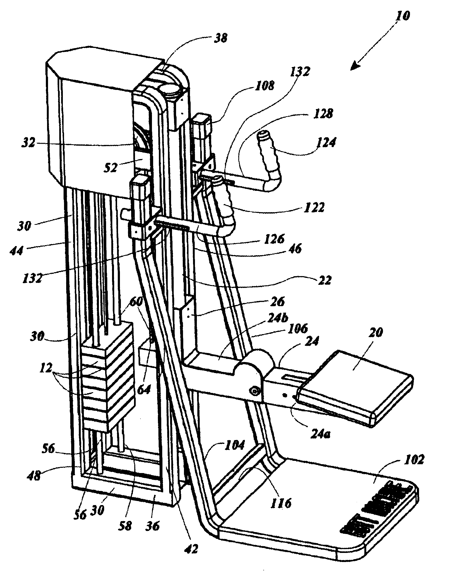
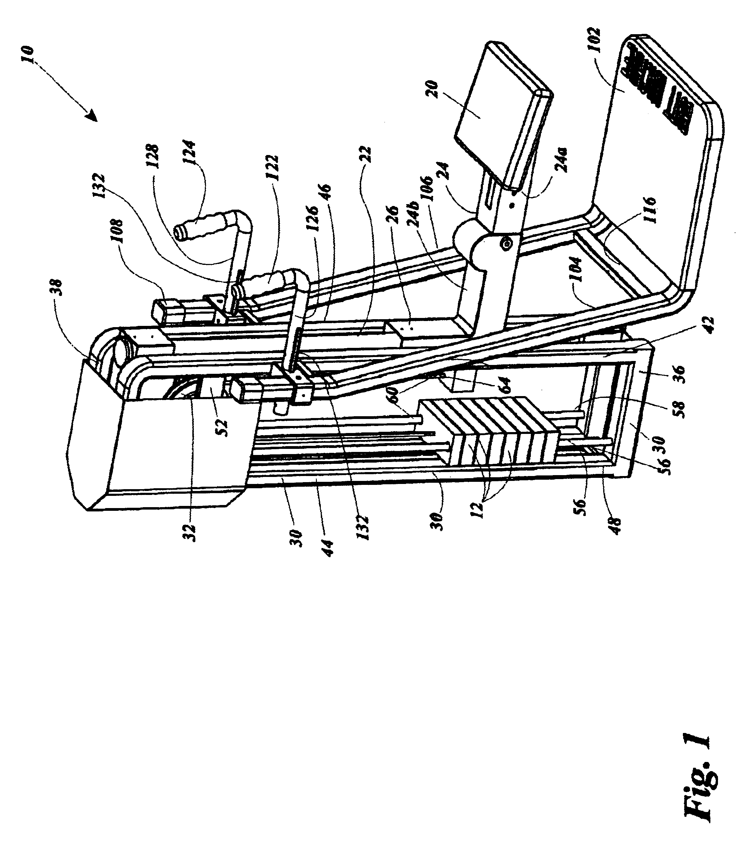
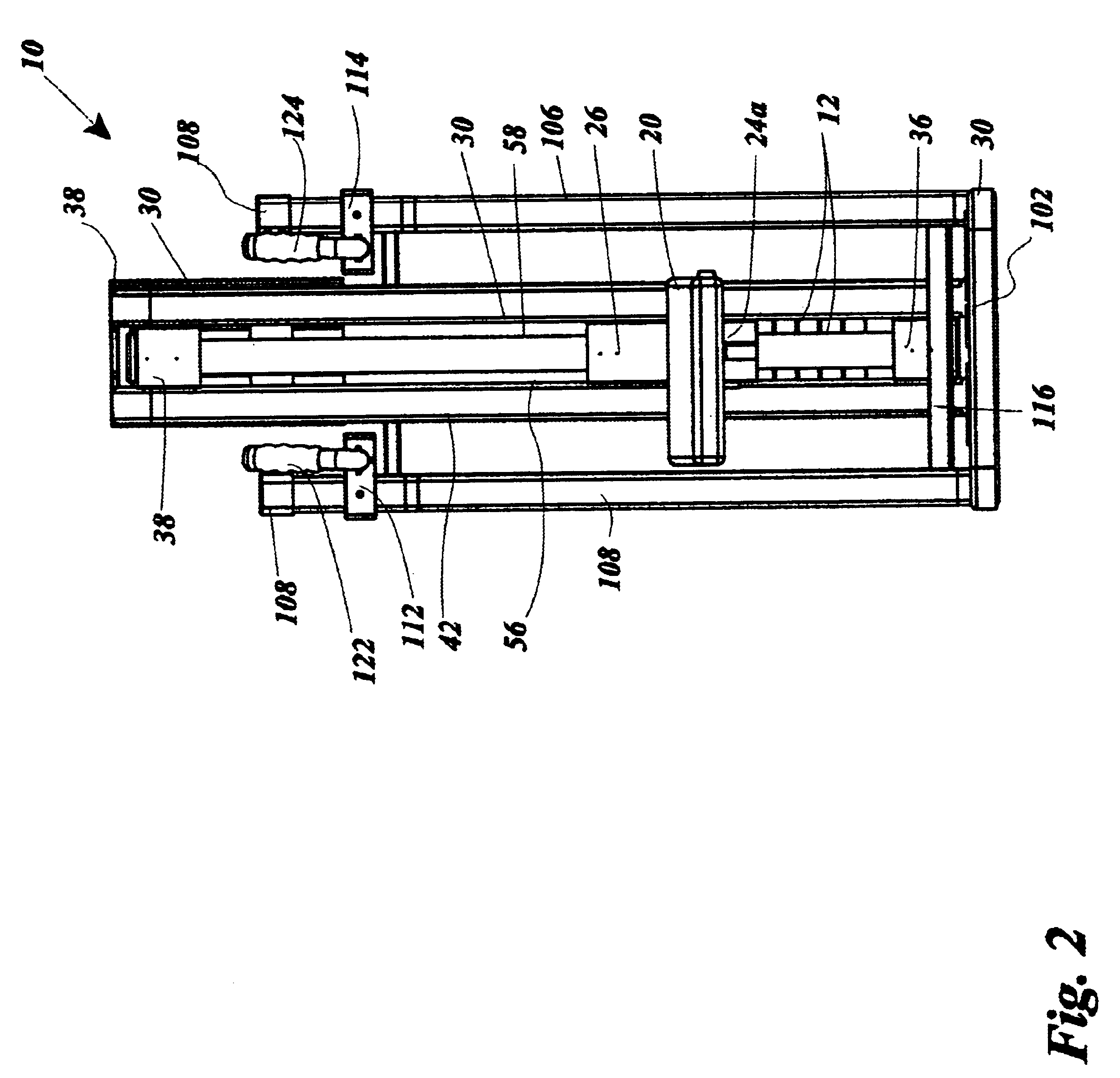
Referring to FIGS. 1-18, an exercise machine 10 is disclosed for exercising the hamstrings, the machine 10 having at least one movement resistance weight 12 and a weight support surface 14 below the weight 12, a weight displacement pedal 20 slidably mounted to an upright pedal guide shaft 22, a machine frame 30 and a pulley 32 rotatably mounted on a pulley axle 34 secured to the machine frame 30 at a position above the lifting weight 12 and above the weight displacement pedal 20, a cable 60 extending over and riding on pulley 32, having a cable distal end 62 secured to the weight 12 and having a cable proximal end 64 secured to weight displacement pedal 20, the cable 60 being of a length relative to the elevation of pulley 32 such that when the weight 12 is resting on weight support surface 14 the pedal 20 is elevated. The pedal 20 preferably includes a pedal brake 70 biased with brake engagement biasing means 72 which engages the pedal guide shaft 22 when pedal 20 is at rest, and w...


PUM


Abstract

An exercise machine for exercising the hamstrings includes at least one weight; a weight support surface below the weight; an upright weight guide shaft laterally spaced apart from the weight; a weight displacement pedal slidably mounted to the pedal guide shaft; a machine frame; a generally horizontal pulley axle secured to the machine frame at a position higher than the weight and higher than the weight displacement pedal and laterally between the weight and the pedal guide shaft; a pulley mounted on the pulley axle so that the pulley is rotatable relative to the machine frame; a cable extending over and riding on the pulley and having a cable distal end secured to the weight and having a cable proximal end secured to the weight displacement pedal, the cable being of a length so that when the weight rests on the weight support surface the weight displacement pedal is elevated.

Description

1. Field of the InventionThe present invention relates generally to the field of exercise equipment. More specifically the present invention relates to an exercise machine for exercising the hamstrings, the machine having at least one movement resistance weight and a weight support surface positioned below the weight, a weight displacement pedal slidably mounted to an upright pedal guide shaft, a machine frame and a pulley rotatably mounted on a pulley axle secured relative to the machine frame at a position above the at least one lifting weight and also above the weight displacement pedal, a cable having a cable distal end secured to the weight and having a cable proximal end secured to the weight displacement pedal, the cable being of a length relative to the elevation of the pulley such that when the weight is resting on the weight support surface the pedal is elevated above its rest position. The pedal preferably includes a pedal brake biased with brake engagement biasing means ...

Claims


Application Information

Patent Timeline
Patent Type & Authority Patents(United States)
IPC IPC(8): A63B21/062A63B21/06A63B23/04
CPCA63B21/062A63B23/0405A63B23/03508A63B2208/029A63B21/0628
Inventor TAYLOR, VINCENT ANTHONYANTHONY, MICHAEL M.
Owner TAYLOR VINCENT ANTHONY
Learn More