Fiber optic with high strength component

a fiber optic and high-strength technology, applied in the direction of optics, fibre mechanical structures, instruments, etc., can solve the problems of inability to access the fiber, damage to the embedded optical fibers, and inability to achieve optical attenuation at the level of inconvenient to achieve the effect of high optical attenuation

Inactive Publication Date: 2004-03-30
CORNING OPTICAL COMM LLC
View PDF35 Cites 95 Cited by
  • Summary
  • Abstract
  • Description
  • Claims
  • Application Information

AI Technical Summary

Problems solved by technology

For example, because the optical fiber is surrounded by the electrically conductive strength member, it is difficult to access the fiber.
Moreover, accessing the central optical fiber can result in damage to the embedded optical fibers.
Although this known fiber optic cable is designed to prevent mechanical stresses on the optical fiber, this design has several disadvantages.
Additionally, twisting introduces stresses on the optical fiber that can cause undesrirable levels of optical attenuation.

Method used


Image

  • Fiber optic with high strength component
  • Fiber optic with high strength component
  • Fiber optic with high strength component

Examples


Embodiment Construction

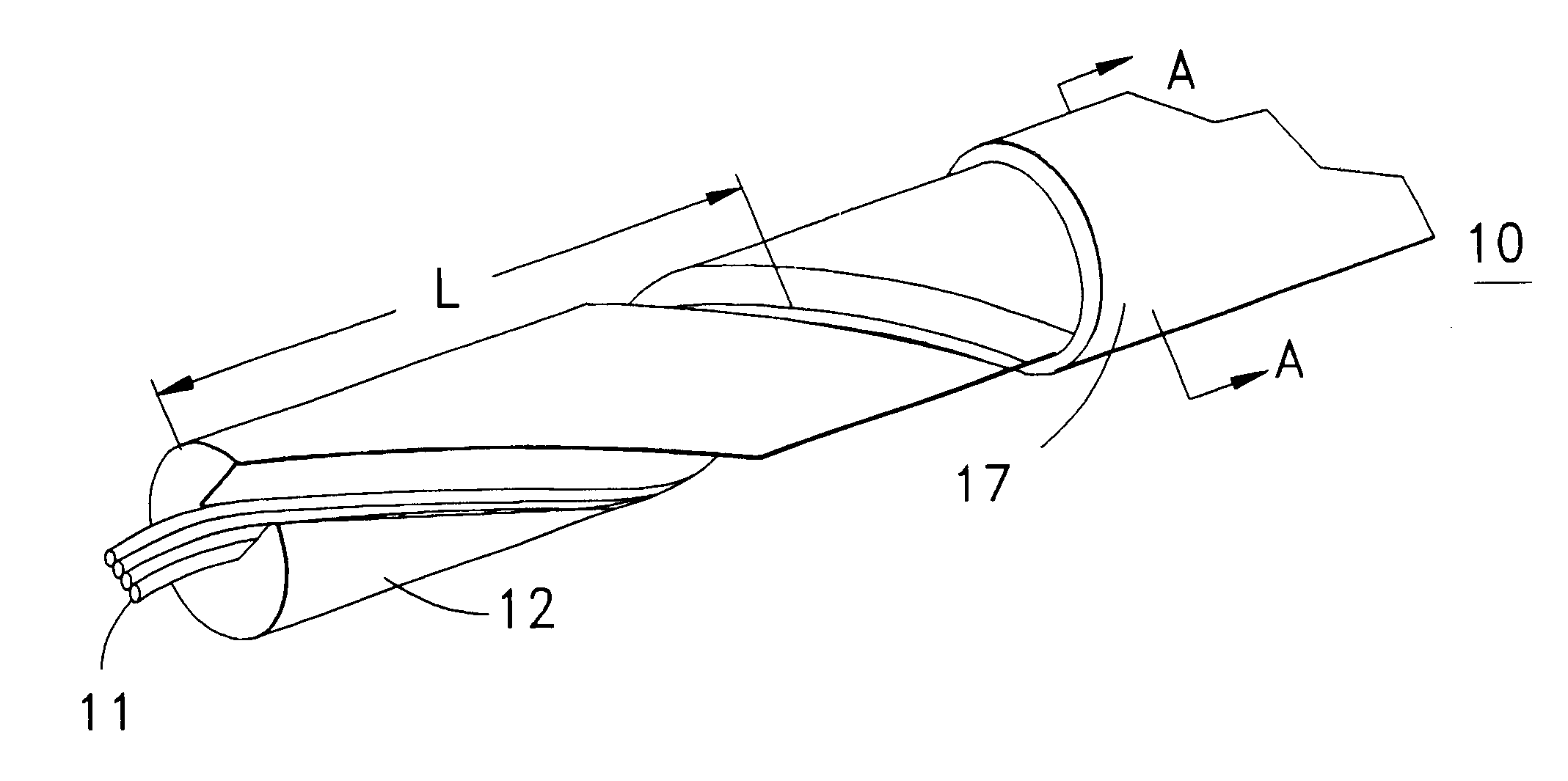
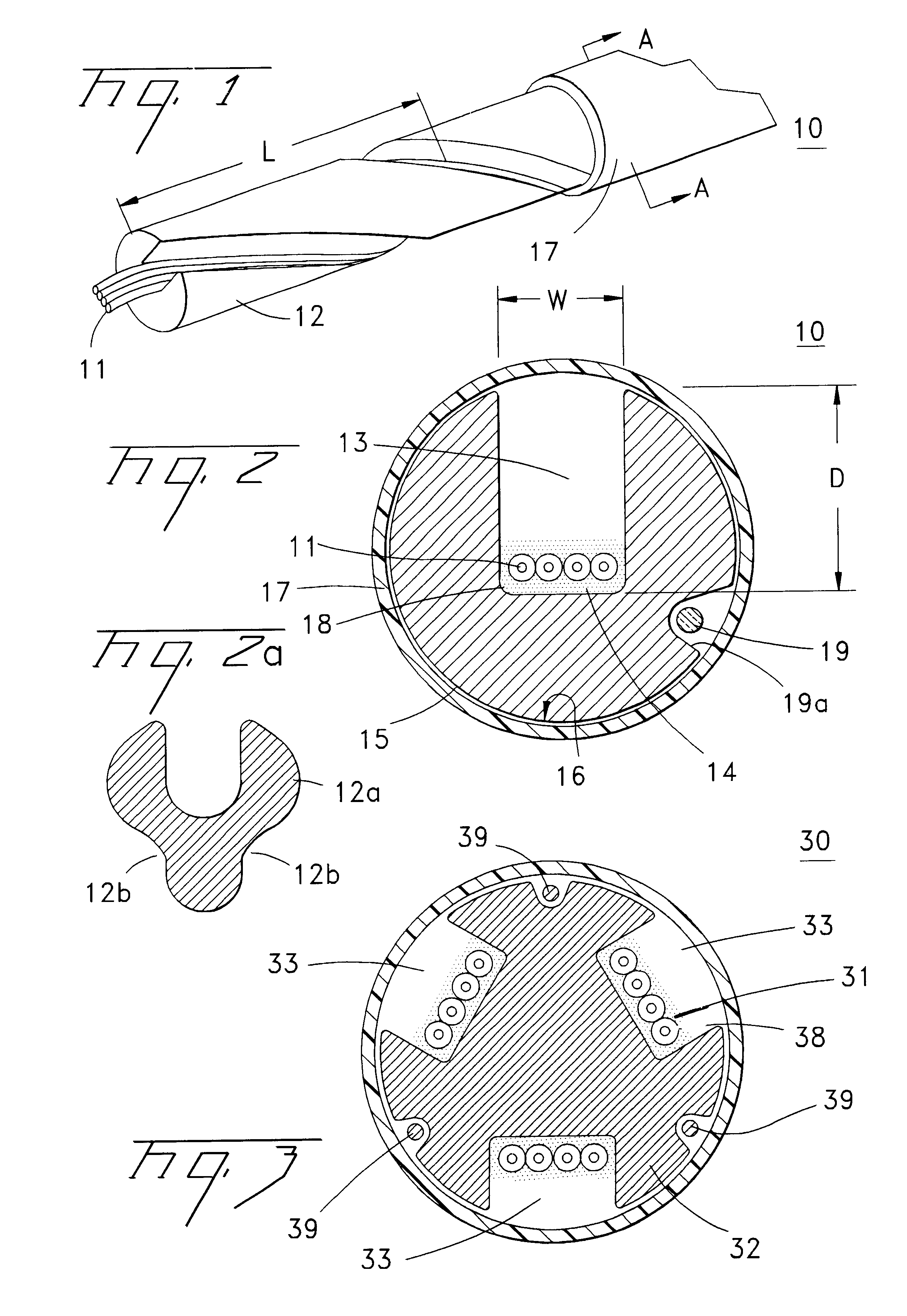
A fiber optic cable 10 according to an embodiment of the present invention is depicted in FIGS. 1 and 2. Fiber optic cable 10 includes at least one optical fiber component 11 disposed within a retention area 13 of a support member 12. Retention area 13 preferably has a generally helical lay of specified length `L`. A cable jacket 17 substantially surrounds optical fiber component 11 and support member 12. A cushioning zone 18 can be disposed adjacent to the optical fiber component, and a water-blocking component 19 can be enclosed by the cable jacket 17.

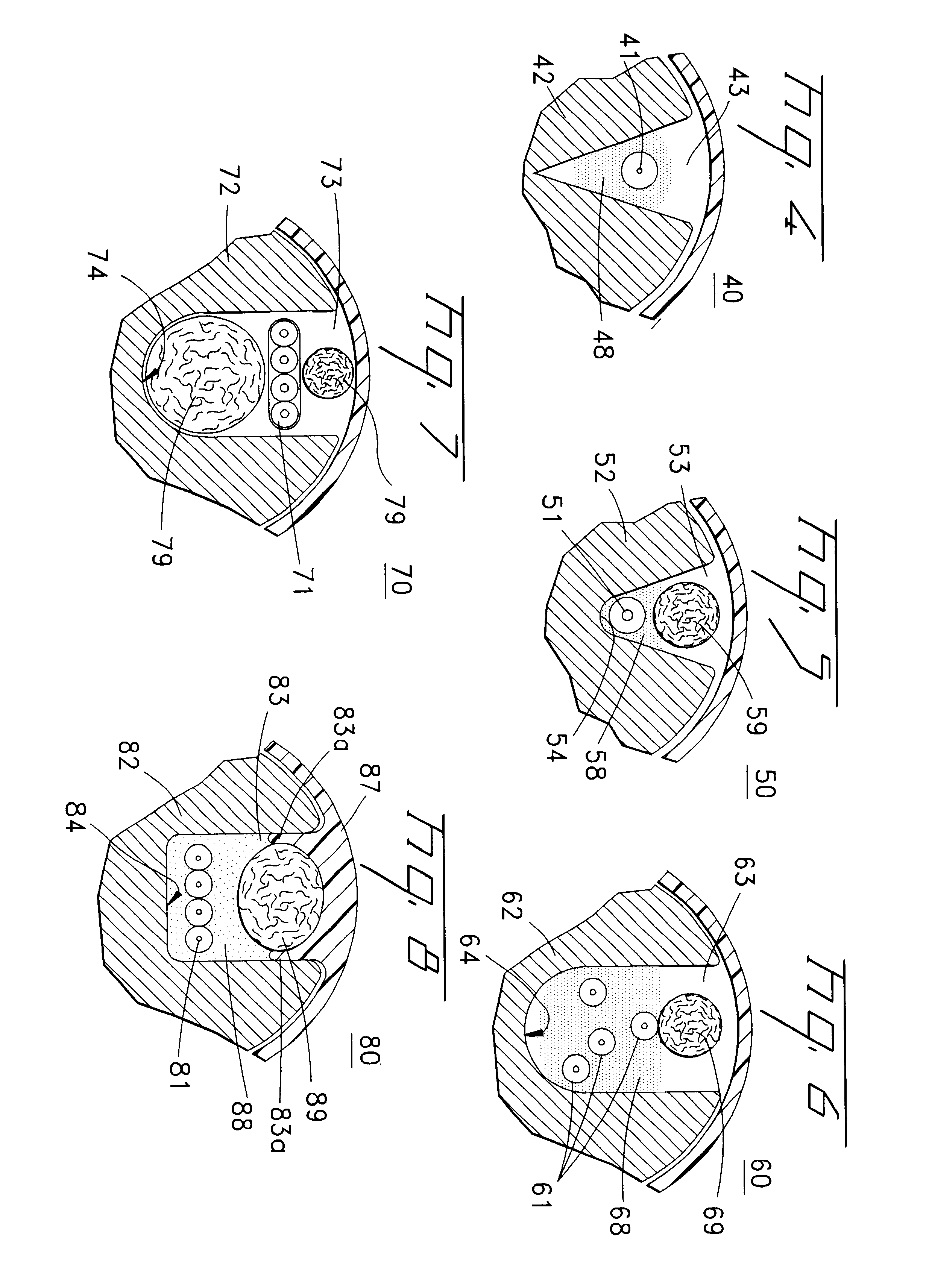
Optical fiber component 11 preferably comprises at least one loose optical fiber. However, component 11 can be tight buffered optical fibers, bundled or ribbonized optical fibers in a common matrix, a stack of optical fiber ribbons in a common matrix or any combination thereof. Each optical fiber preferably includes a silica-based core that is operative to transmit light and is surrounded by a silica-based cladding having a lower ind...


PUM


Abstract

A fiber optic cable having at least one optical fiber component disposed within at least one retention area of a support member. The support member including a metallic or dielectric material having the retention area disposed generally helically relative to a longitudinal axis of the cable. The cable also includes an interfacial layer between an outer surface of the support member and a cable jacket substantially surrounding the support member. The cable can include a cushioning zone adjacent the optical fiber component, and / or a water-blocking component between an outer surface of the support member and the cable jacket. The support member can have at least one bendable tab for at least partially covering the retention area.

Description

The present invention relates generally to fiber optic cables and, more particularly, to fiber optic drop cables.Fiber optic cables include optical fibers that are capable of transmitting voice, video, and data signals. Fiber optic cables have advantages over electrical voice, video and data signal carriers, for example, increased data capacity. As businesses and households demand increased data capacity, fiber optic cables can eventually displace electrical voice, video, and data signal carriers. This demand will require low fiber count optical cables to be routed to end users, for example, businesses and households.Fiber optic cables can typically be used in various applications. For example, fiber optic drop cables can be suitable for both aerial and buried cable applications. More specifically, a fiber optic drop cable can be strung between poles and / or buried in the ground before reaching the end user. Aerial and buried cable environments have unique requirements and considerat...

Claims


Application Information

Patent Timeline
Patent Type & Authority Patents(United States)
IPC IPC(8): G02B6/44
CPCG02B6/4407G02B6/4489
Inventor MCALPINE, WARREN W.FIELD, LARRY W.
Owner CORNING OPTICAL COMM LLC
Why Eureka
Try Eureka