Pinwheel

a technology of pinwheel and blade, applied in the field of pinwheel, can solve the problems of limited play with the conventional pinwheel, unsatisfactory, and inconvenient use, and achieve the effect of not being particularly attractive to the market, and reducing the number of blades

Inactive Publication Date: 2004-04-06
CHEN PAN HAI LUNG
View PDF5 Cites 27 Cited by
  • Summary
  • Abstract
  • Description
  • Claims
  • Application Information

AI Technical Summary

Problems solved by technology

To play with the conventional pinwheel is limited and is not enjoyable.
In addition, the conventional pinwheel usually has only one layer of blades (34), such that...

Method used


Image

  • Pinwheel
  • Pinwheel
  • Pinwheel

Examples


Embodiment Construction

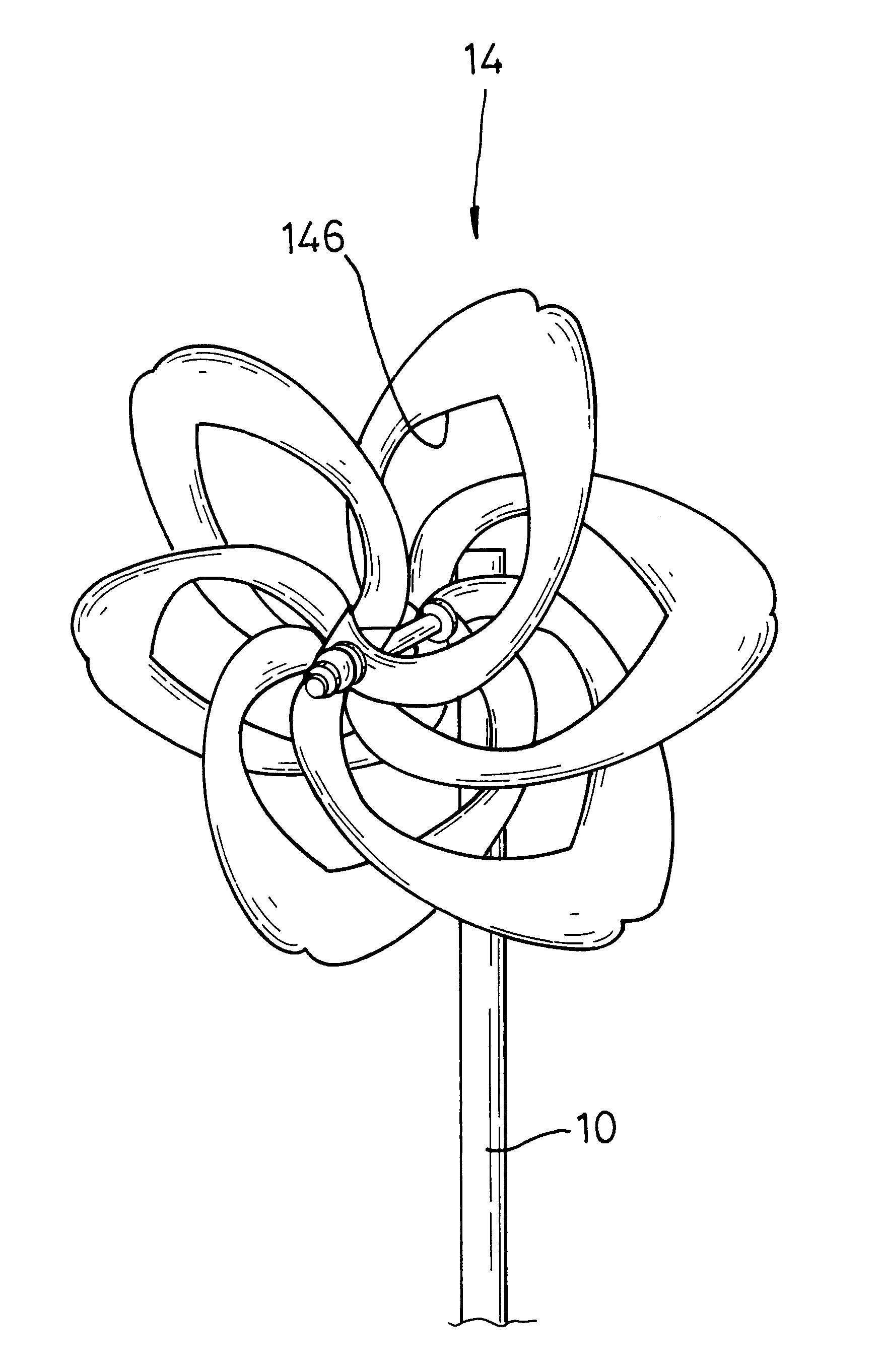
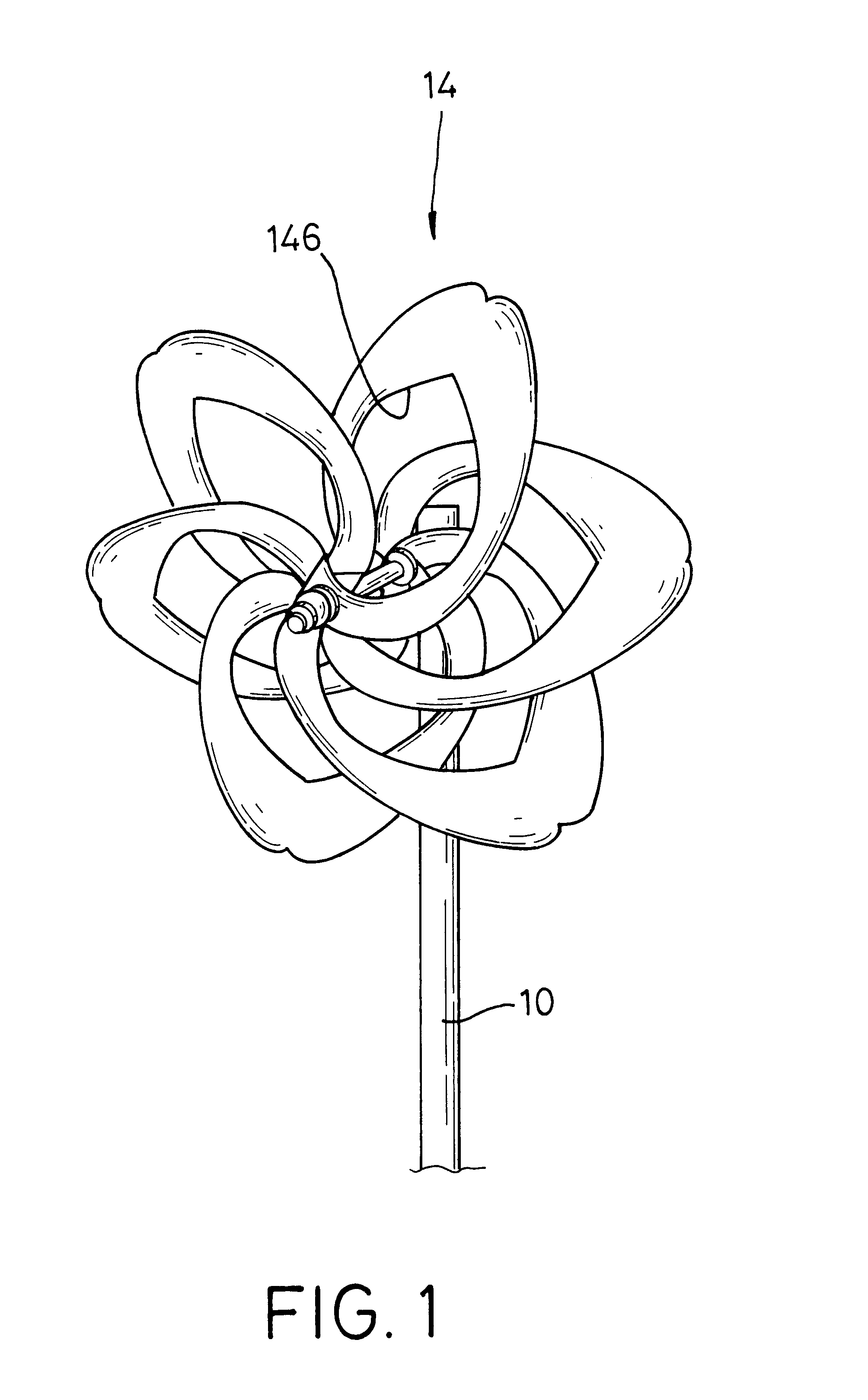
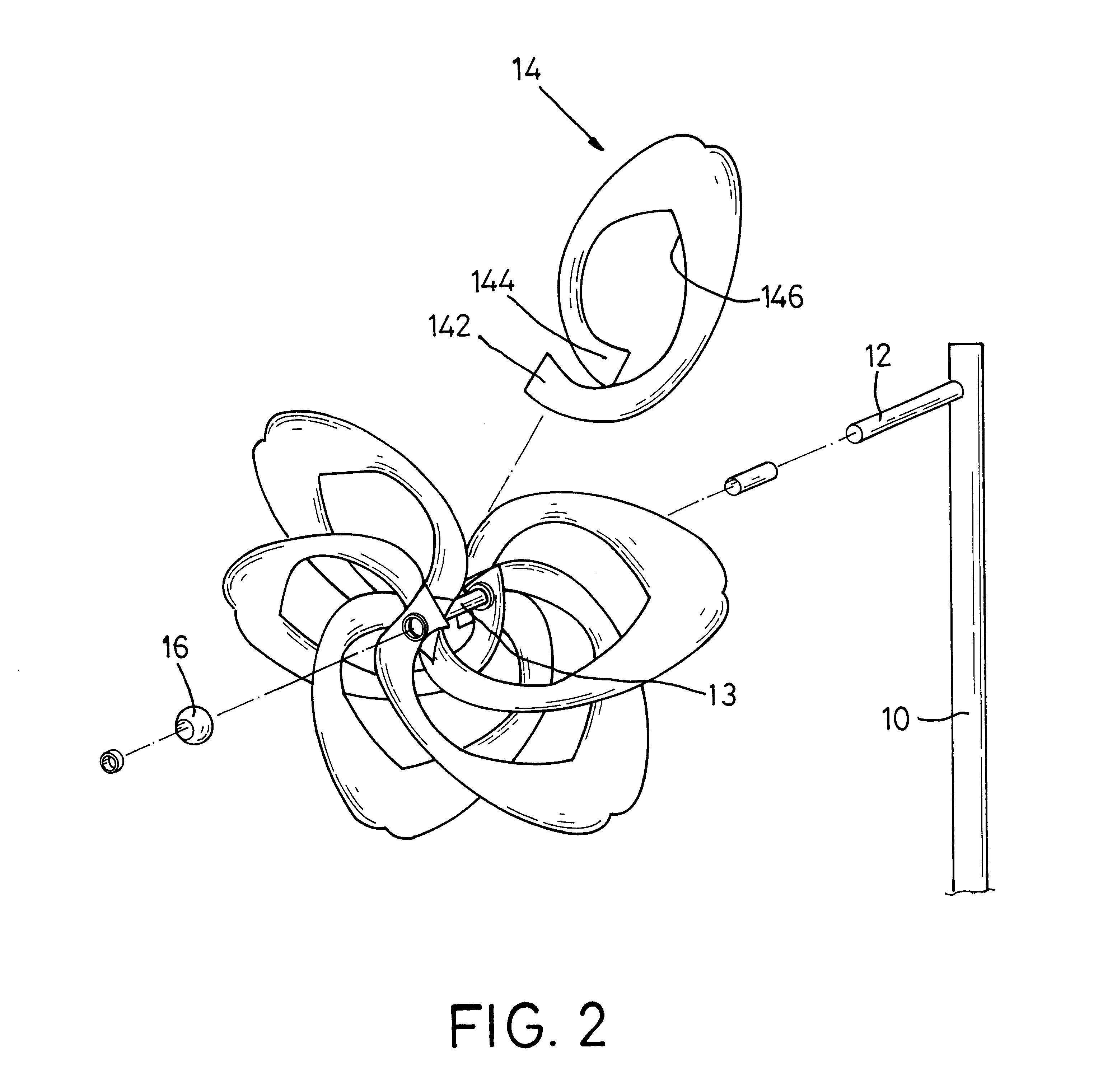
With reference to FIGS. 1 to 3, a pinwheel in accordance with the present invention comprises a rod (10), a shaft (12) and multiple blade elements (14). The shaft (12) is perpendicularly attached to the rod (10) near the top of the rod (10). The blade elements (14) are rotatably connected to the shaft (12). In practice, a sleeve (13) is rotatably mounted around the shaft (12), and the blade elements (14) are securely attached to the sleeve (13j so as to be pat rotatably connected to the shaft (12) through the sleeve (13). Each blade element (14) has two ends (142,144) respectively attached to two ends of the sleeve (13). A cutout (146) is defined in each respective blade element (14), such that the blade element (14) has a large passage to allow the wind to pass through the passage in the blade element (14). Accordingly, there are many contact areas formed on each blade element (14) facing in different directions. Each blade element (14) can be made of a resilient material, such as ...


PUM


Abstract

A pinwheel has a rod, a shaft and multiple blade elements. The blade elements are rotatably attached to the shaft, and each blade element has a cutout so as to define a passage for wind passing therethrough in the blade element. In such a pinwheel, the blade elements can be actuated to rotate in any direction of wind passing through the pinwheel. In addition, multiple layers of blade elements can be mounted in the shaft to make the appearance of the pinwheel versatile.

Description

1. Field of the InventionThe present invention relates to a pinwheel, and more particularly to a pinwheel with a versatile appearance.2. Description of Related ArtWith reference to FIG. 5, a conventional pinwheel in accordance with the prior art substantially comprises a rod (30), a shaft (32) and multiple blades (34). The shaft (32) is perpendicularly attached to the rod (30) near the top of the rod (30). The blades (34) are rotatably attached to the shaft (32). In practice, each blade (34) of the conventional pinwheel is a flat element with a large area and is bent to connect to two ends of the shaft with two ends of each blade (34) so as to form a contact area on the blade (34). When wind passes through the pinwheel and hits the contact areas on the blades (34), the blades (34) will be actuated to rotate by the wind. Additionally, the blades (34) will be actuated to rotate by means of blowing by the user, and an enjoyment will be provided to the user.However, to actuate the blade...

Claims


Application Information

Patent Timeline
IPC IPC(8): A63H33/00A63H33/40
CPCA63H33/40
Inventor CHEN PAN, HAI-LUNG
Owner CHEN PAN HAI LUNG
Why Eureka
Try Eureka