
Subsurface monitoring and borehole placement using a modified tubular equipped with tilted or transverse magnetic dipoles

a technology of magnetic dipoles and subsurface monitoring, which is applied in the direction of surveying, borehole/well accessories, instruments, etc., can solve the problems of shallow depth of investigation, adversely affecting the extraction of petroleum, and low porosity accuracy

Inactive Publication Date: 2004-04-27
SCHLUMBERGER TECH CORP
View PDF18 Cites 32 Cited by
  • Summary
  • Abstract
  • Description
  • Claims
  • Application Information

AI Technical Summary

Problems solved by technology

Such migration can adversely affect the extraction of petroleum by creating pockets that are missed by the producer and by saturating the oil deposits with water.
The primary disadvantages of such pulsed neutron measurements are shallow depth of investigation and low accuracy in low porosities.
However, this technique is presently limited to closely spaced wells with either open-hole completions or cased with insulating composites.
The disadvantages of these systems include the fragility and expense of fiberglass casing, making the technique impractical for use in production wells.
Moreover, drilling a special well for monitoring is very expensive and therefore rarely done.
Its disadvantages include: the fragility of the external hardware and cable, the difficulty of running a complex completion into the well, the logistics of running a wire outside of the casing from surface to downhole, the inability to repair damaged or malfunctioning components, the difficulty to guarantee a hydraulic seal between the casing and the formation with external cables present, the possibility of cross-talk between these cables, the difficulty to place preamplifiers and other electronics near the electrodes, electrode impedance effects, and the influence of the cement annulus on resistivity.
However, these types of slotted tubes or liners are not cemented in the wellbore, and do not provide hydraulic isolation from one well section to another.
These technologies have not been readily applicable to measurement and monitoring techniques using steel-cased production wells.
The steel casing dramatically attenuates electromagnetic (EM) signals, restricting the possible use of known techniques primarily to qualitative detection of high resistive zones, but not for quantitative saturation measurements.

Method used


Image

  • Subsurface monitoring and borehole placement using a modified tubular equipped with tilted or transverse magnetic dipoles
  • Subsurface monitoring and borehole placement using a modified tubular equipped with tilted or transverse magnetic dipoles
  • Subsurface monitoring and borehole placement using a modified tubular equipped with tilted or transverse magnetic dipoles

Examples


Embodiment Construction

4.1 Slotted Tubular

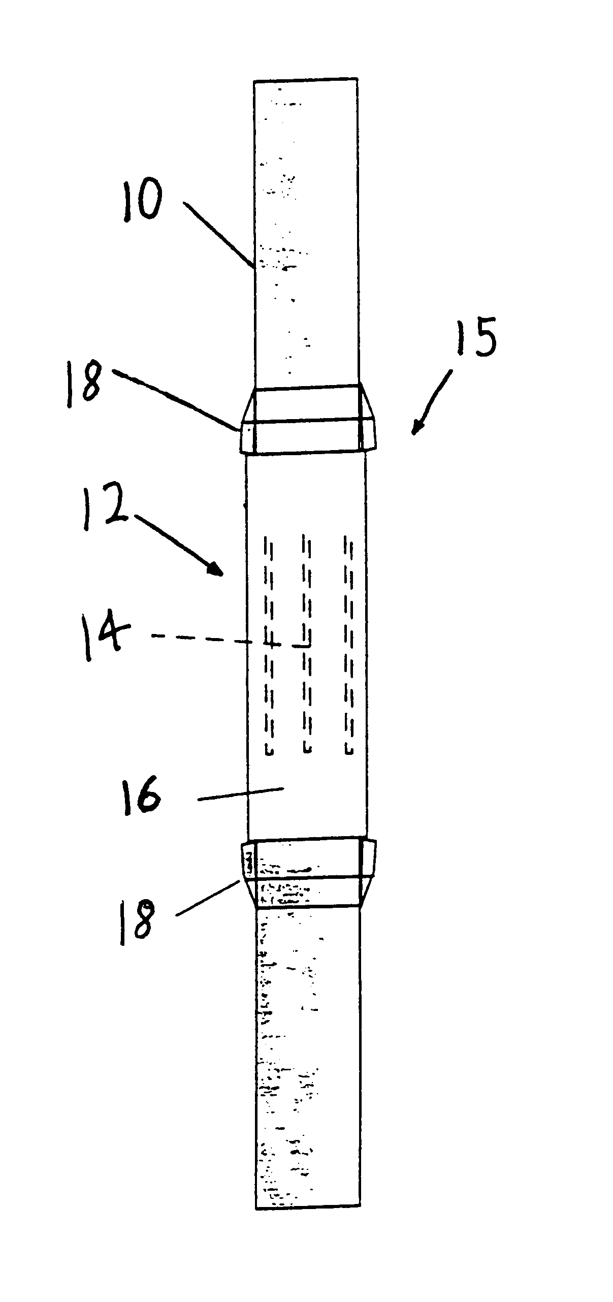
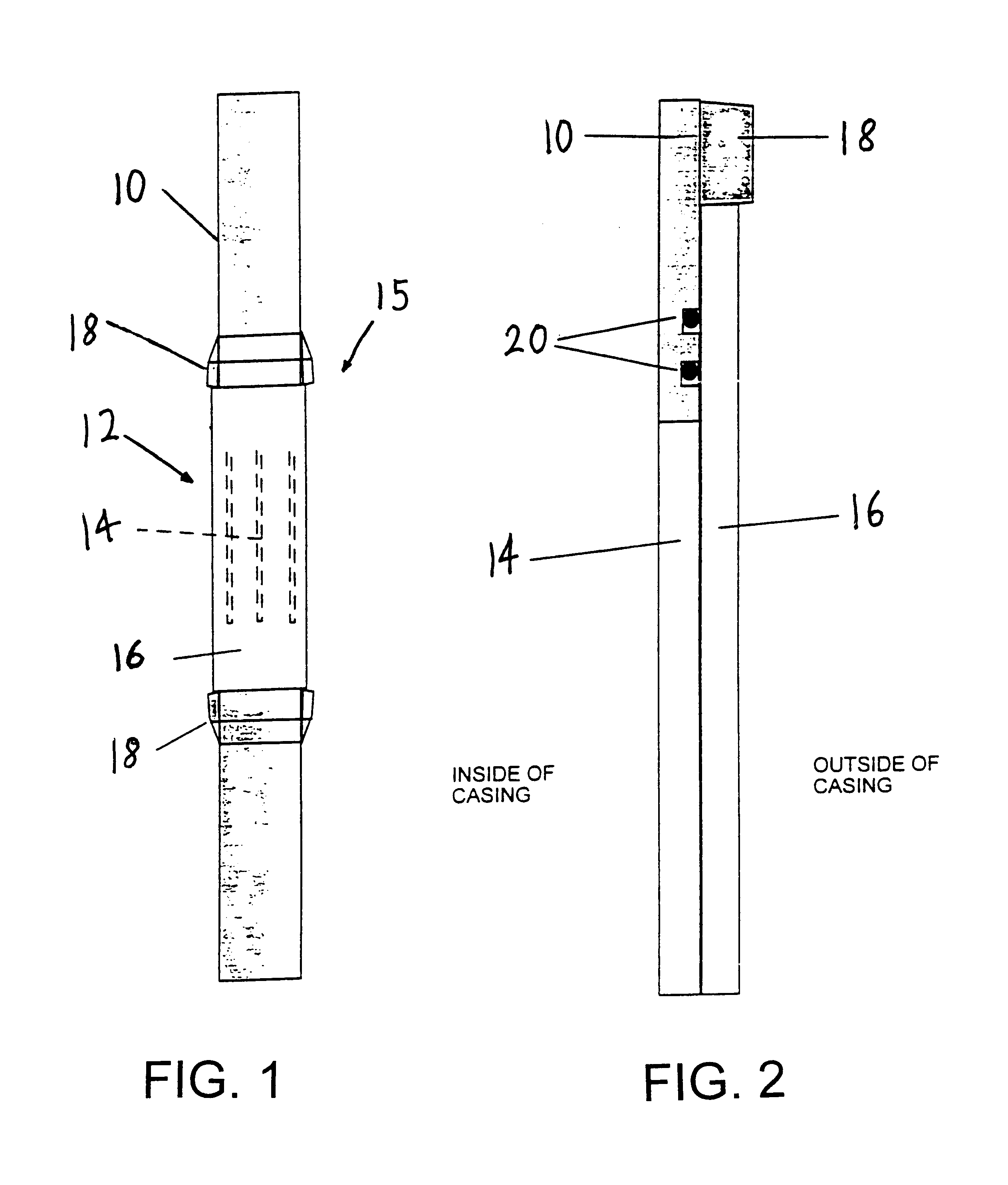
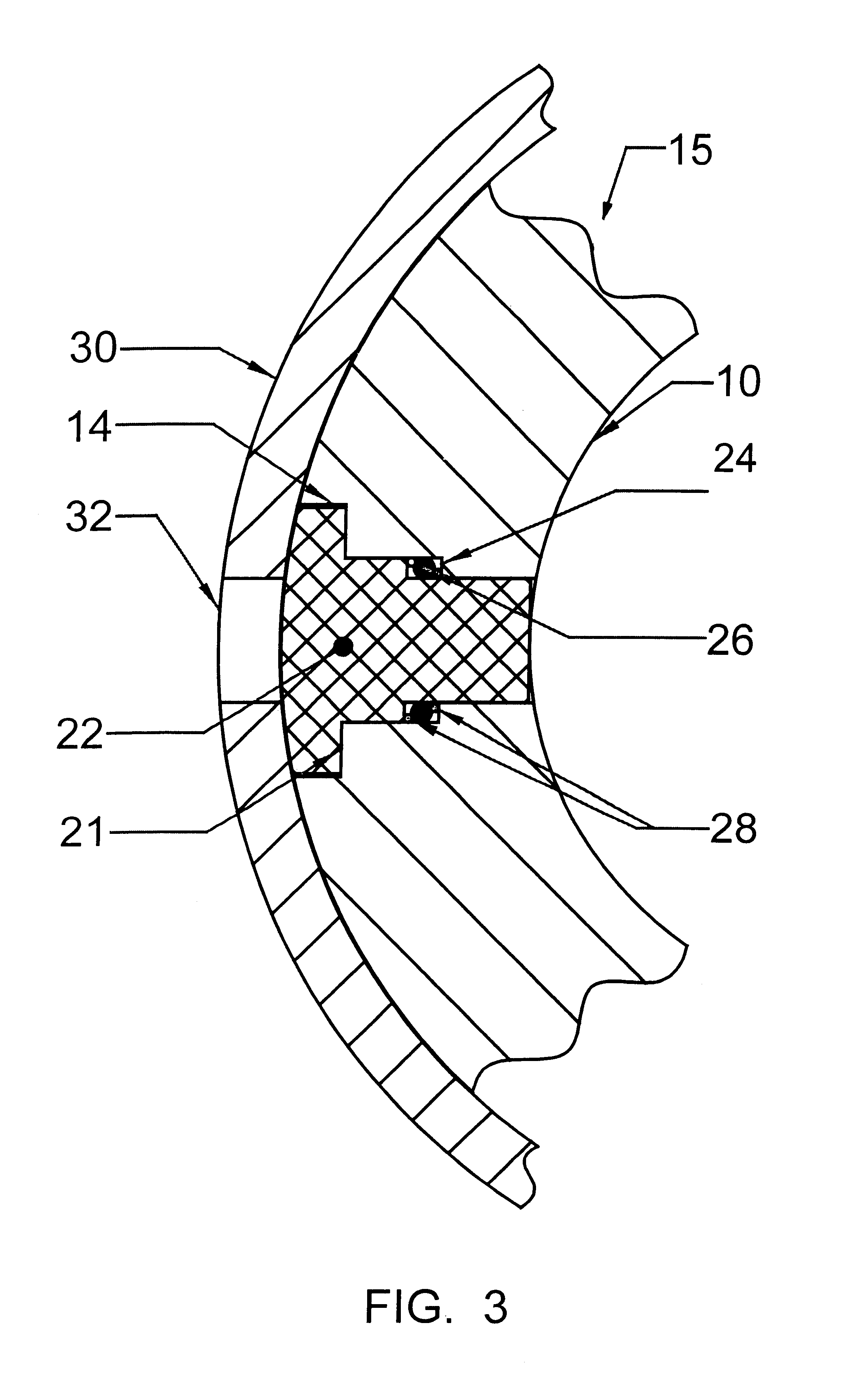
FIG. 1 shows a tubular or casing 10 segment of the invention. The metal tubular 10 includes a station 12 with axial slots 14 cut through the tubular wall. Each elongated axial slot 14 fully penetrates the tubular wall of the casing 10. Hydraulic isolation between the interior and exterior of the casing 10 is provided by an insulating structure 15. The structure 15 includes an insulator 16 formed in the shape of a cylindrical tube or sleeve to enclose the slotted station 12. FIG. 2 shows a cross section of an insulator 16 placed over a slot 14 on the exterior of the casing 10. The insulator 16 is slid over the slots 14 with one or more O-rings 20 providing a seal. Alternatively, the insulator 16 may be placed inside the tubular casing 10, rather than outside (not shown).

The insulator 16 is made of a nonconductive material, permitting the passage of EM energy. Useable materials include the class of polyetherketones described in U.S. Pat. No. 4,320,224, or other suit...


PUM


Abstract

Systems and methods for monitoring a subsurface formation property and for placing a borehole in the vicinity of a well in the formation. A slotted tubular is utilized to provide through-tubular signal transmission and / or reception using an antenna adapted to generate a magnetic dipole moment with a transverse or controllable orientation. Hydraulic isolation between the interior and exterior of the tubular at the slot is provided by a pressure barrier. The tubular also forms part of a system for accurately placing a well within a desired distance and orientation relative to an existing well.

Description

1. BACKGROUND OF THE INVENTION1.1 Field of the InventionThis invention relates generally to the investigation of subsurface earth formations, and, more particularly, to techniques for monitoring formation properties and to place wells with greater accuracy using tilted or transverse magnetic dipole sources or sensors housed within a modified tubular. This invention is applicable to induction or propagation type measurements, i.e., at low and high frequencies.1.2 Description of Related ArtPetroleum is usually produced from oil reservoirs sufficiently far below a gas cap and above an aquifer. As the oil zone is being produced and depleted, the gas cap starts coning downward and the aquifer coning upwards towards the oil-bearing zone. Such migration can adversely affect the extraction of petroleum by creating pockets that are missed by the producer and by saturating the oil deposits with water. As soon as either gas or water hits the well, its oil production usually ceases instantly.Re...

Claims


Application Information

Patent Timeline
Patent Type & Authority Patents(United States)
IPC IPC(8): E21B47/16E21B47/12E21B43/02E21B43/08E21B47/01E21B47/00G01V3/30G01V3/18
CPCE21B43/086E21B47/011E21B47/122E21B47/16G01V3/30E21B47/017E21B47/13
Inventor FREY, MARK T.OMERAGIC, DZEVATTABANOU, JACQUES R.
Owner SCHLUMBERGER TECH CORP
Learn More