Champagne cork remover

a cork remover and champagne technology, applied in the field of champagne cork remover, can solve the problems of large complex machines, affecting the work efficiency of workers, and affecting the quality of champagne cork removal,

Inactive Publication Date: 2004-05-18
MCLUEN CARL T
View PDF18 Cites 1 Cited by
  • Summary
  • Abstract
  • Description
  • Claims
  • Application Information

AI Technical Summary

Benefits of technology

a) to provide a champagne cork remover which can grip and raise a champagne cork with little strength or effort required.
c) to provide a tool which can retain the cork or other stopper as it exits the bottle.
d) to provide a simple, uncomplicated design which can be produced and sold at low cost.
e) To provide a device which can also remove plastic bottle stoppers used for sparkling cider, and similar beverages, sold in champagne size bottles.
f) to enable wine stewards to quickly serve champagne formally, and with ease and grace, in restaurants and dining rooms.

Problems solved by technology

In all of these, the problem is not the force required to dislodge the cork stopper, but rather it is in the means of applying it to the soft and frangible part of the cork which is exposed.
Teeth forced into the uncompressed cork can tear or fracture the cap, leaving even less to work with.
Most champagne is opened at the table in restaurants or private homes, and large complicated machines, such as that of John Mueller noted above, are unsuitable for such use.
Most of these prior art devices fail to achieve their objective due to the problem of effectively connecting to the cork stopper without damaging it.

Method used


Image

  • Champagne cork remover
  • Champagne cork remover
  • Champagne cork remover

Examples


Embodiment Construction

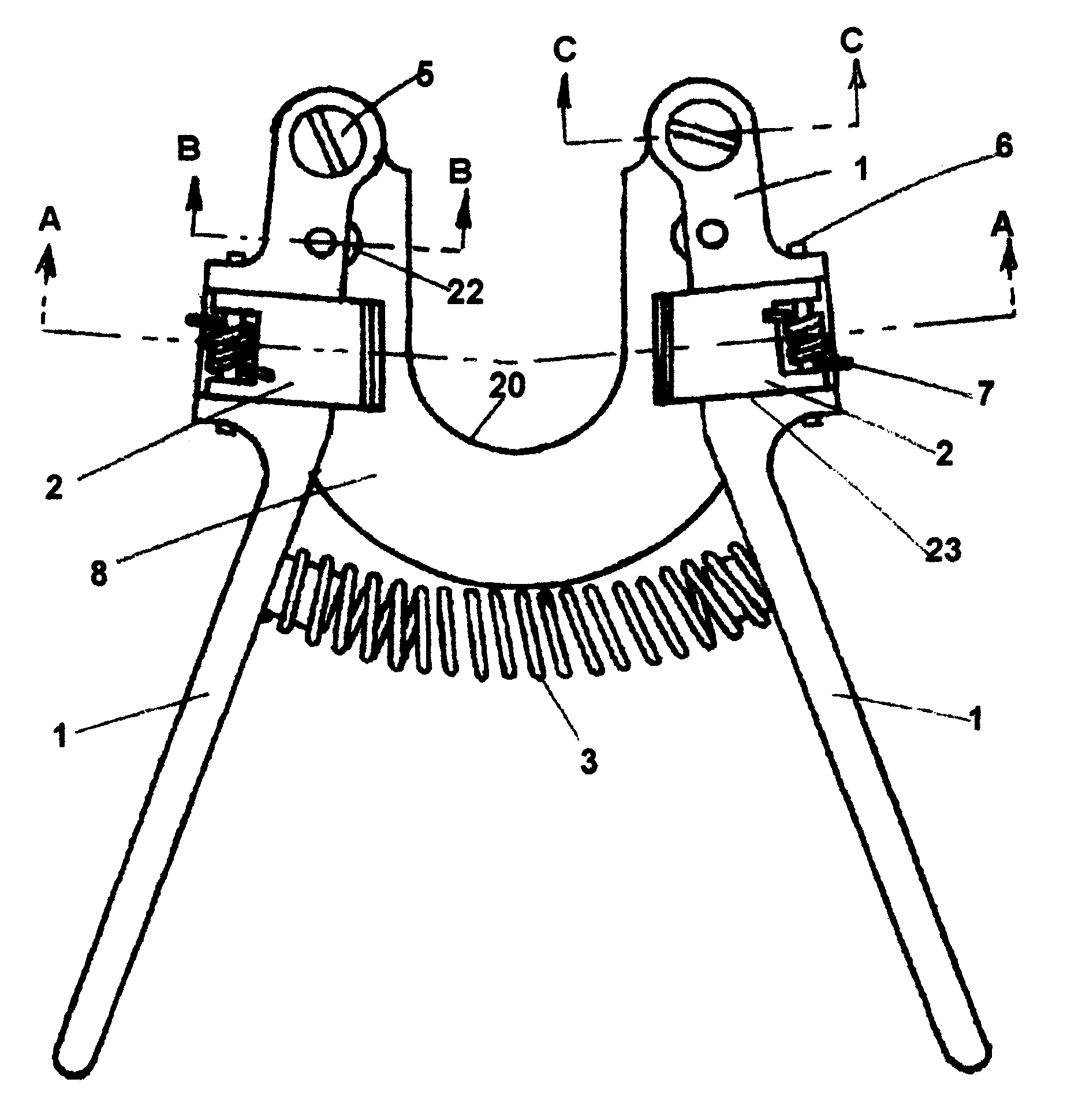
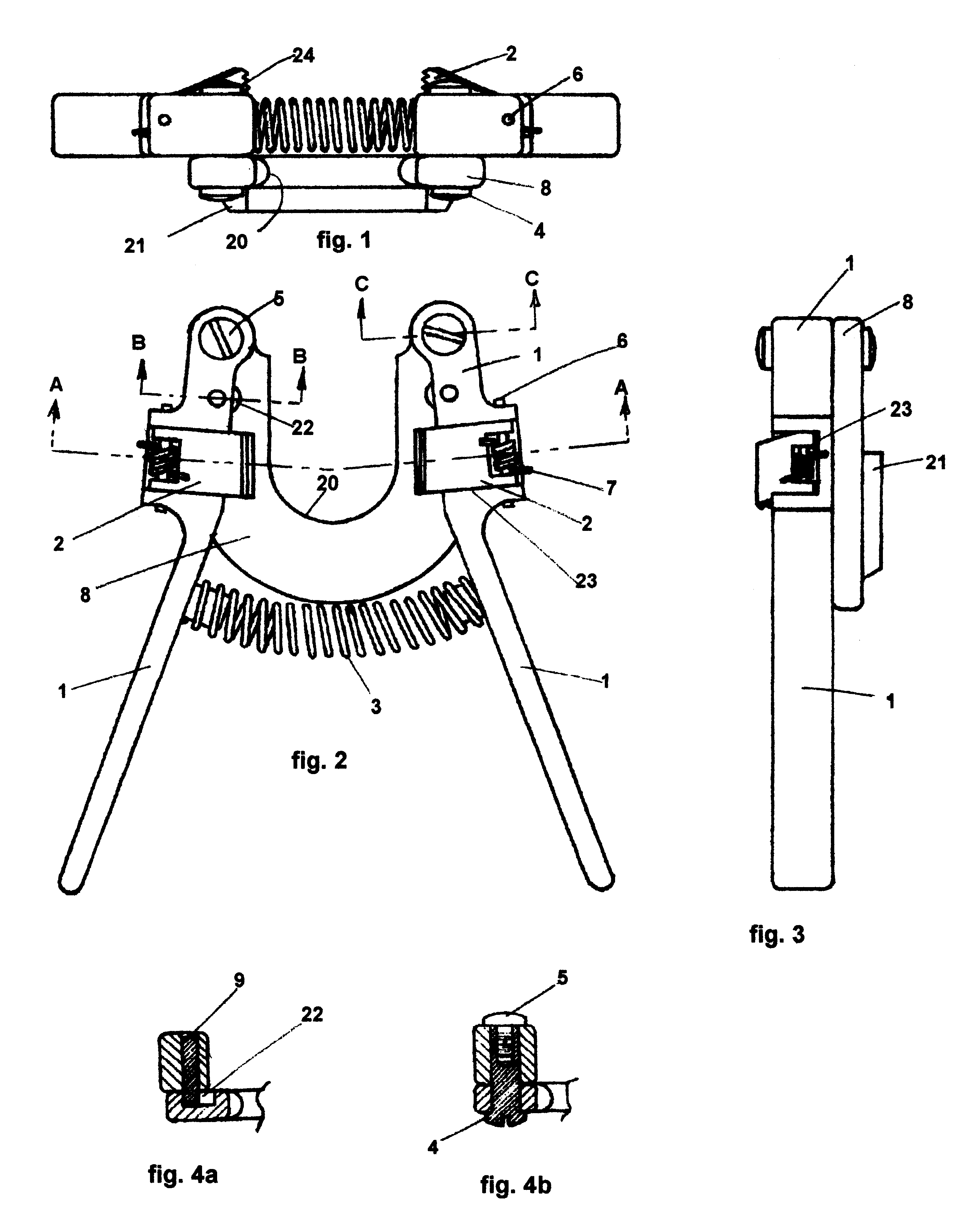
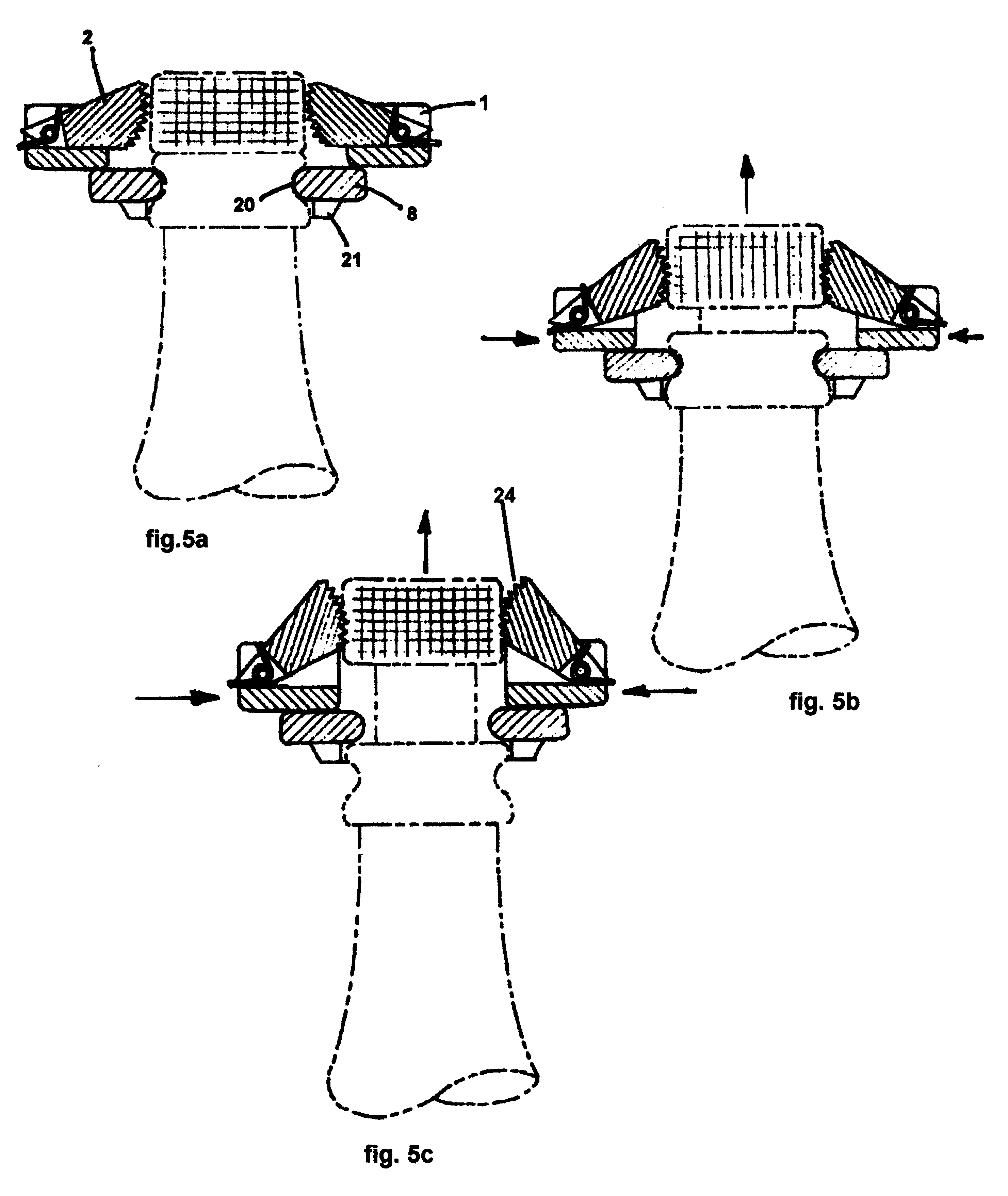
The preferred embodiment of this invention is illustrated in the three views of FIG. 1, FIG. 2, and FIG. 3. The lever-arms 1, shown in all three views, are connected to the base plate 8, by two pivots 4 These are kept in place by fillister head screws 5. The pivots 4, are a close but loose fit into the lever-arms 1, and of a length that allows free angular movement of the lever-arms. A compression spring 3, fitted between the lever-arms 1, tends to hold them apart. Stop- pins 9, protruding through the lever-arms into the stop- pin cavities 22 serve to constrain angular movement of the lever-arms to within the comfortable manipulation range of the average adult hand. Extractor links 2, are located in channels 23, formed across the lever-arms at a point in line with the center of the radius of the U-shaped cutout 20. Thus located, the extractor links 2, are moved toward the center of the U-shaped cutout 20, when lever-arms 1, are moved together.

The U-shaped cutout 20, of the base plat...


PUM


Abstract

A hand tool with a U-shaped cutout to slide into the groove at the top of a champagne bottle, and pivoted lever-arms above the cutout straddling the stopper of the bottle. Extractor links connected to these lever-arms, are hinged at the outer end, and have teeth across the inner end, which is aligned with the stopper. Squeezing the lever-arms together causes the extractor links to engage and compress that part of the stopper exposed above the top of the bottle. The extractor links are angled upward toward the toothed end, so that the resulting combined upward force of the two links on opposite sides of the stopper, cause it to be extruded upward. Repeated actuations may be used to remove the stopper completely. The tool grips, and retains the stopper when completely closed.

Description

1. Field of the InventionThis invention relates to opening champagne bottles, and the like, by applying a force to the exposed part of the cork, or plastic, stopper.2. Prior ArtA number of devices have been patented to accomplish this task, most of which attempt to pry or pull the stopper out by exerting a force between the top of the bottle and the enlarged part of the cork, which is exposed. Simple lever systems such as those found in U.S. Pat. No. 4,598,613 Jul. 8, 1986 to Frederick W. Baum, U.S. Pat. No. 4,590,821 May 27, 1986 to James C. Olson, and U.S. Pat. No. 4,680,993 Jul. 21, 1987 to Jack M. Feliz, are examples of such devices. Geared lever systems are also used in some designs, such as found in U.S. Pat. No. 4,750,391 Jun. 14, 1988 to Stanley L. Sweath, and U.S. Pat. No. 4,947,711 Aug. 4, 1990 to Ben F. Glebeler. A cranked threaded shaft mated with a threaded tubular column are used to exert the force in U.S. Pat. No. 5,040,437 Aug. 20, 1991 to John H. Mueller.In all of t...

Claims


Application Information

Patent Timeline
Patent Type & Authority Patents(United States)
IPC IPC(8): B67B7/00B67B7/06
CPCB67B7/066
Inventor MCLUEN, CARL T.
Owner MCLUEN CARL T
Why Eureka
Try Eureka