Device for the control of the thrust force of a manually operated pneumatic screw driver

a technology of pneumatic screw driver and thrust force, which is applied in the direction of wrenches, metal working devices, work benches, etc., can solve the problems of increasing substantially, and achieve the effect of simplifying the handling of pneumatic screw drivers and facilitating the operation

Inactive Publication Date: 2004-05-18
FESTO AG & CO KG
View PDF7 Cites 6 Cited by
  • Summary
  • Abstract
  • Description
  • Claims
  • Application Information

AI Technical Summary

Benefits of technology

One object of the invention is to facilitate and simplify the handling of a pneumatic screw driver when performing screwing operations.
Accordingly for screw driving operations may be performed extremely ergonomically with no operator fatigue, something which leads to high quality products despite long periods on the job. The invention is based on the discovery that during the operation of a pneumatic screw driver the operating pressure supplied to it is subject to a slight drop, which is detected by the control means and may be employed as a trigger to reduce the lifting force caused by the drive means or even to switch it off completely.

Problems solved by technology

The result of this is that directly after putting it into operation of the pneumatic screw driver the weight force thereof and possibly the weight forces loading the pneumatic screw driver of the holding device are no longer compensated so that the thrust force, with which the pneumatic screw driver is thrust downward against the screw to be driven, is increased substantially without the application of force by the operator.

Method used


Image

  • Device for the control of the thrust force of a manually operated pneumatic screw driver
  • Device for the control of the thrust force of a manually operated pneumatic screw driver

Examples


Embodiment Construction

.

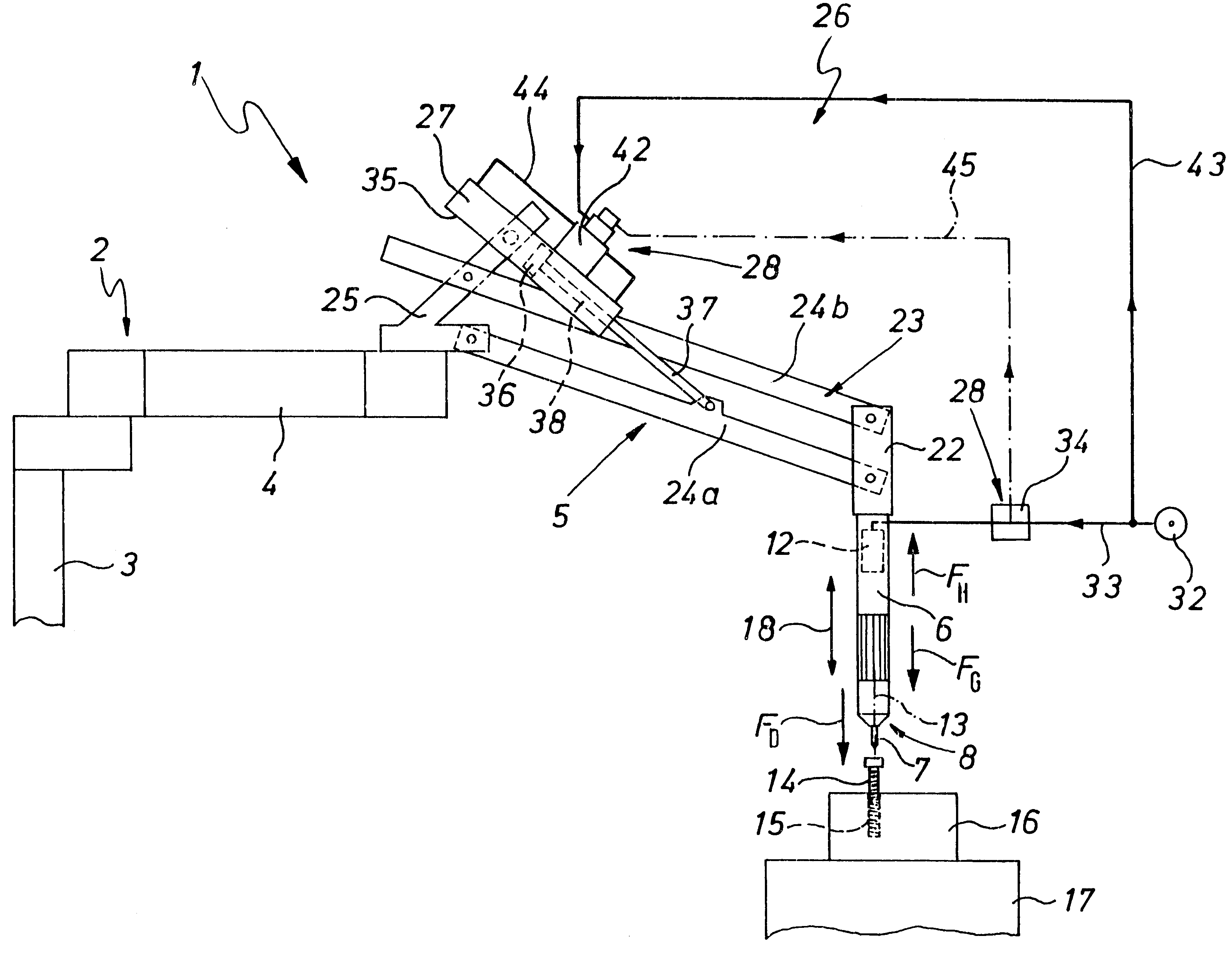
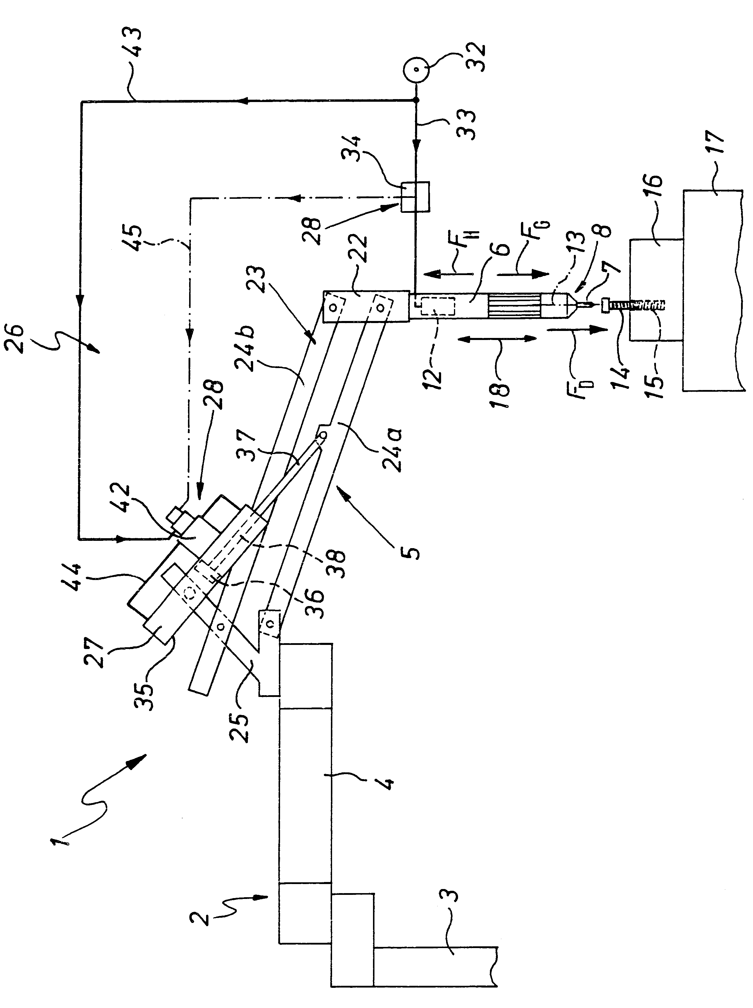
The instrumentality 1 possesses a diagrammatically indicated carrier device 2 provided with an attachment part 3 by way of which it may be stationarily set at the point of application of the instrumentality 1, as for instance on the ground on a wall.

A boom 4 is pivotally mounted on the attachment part 3 and can have one or more joints or bearings so that it may be deflected vertically, that is to say in the drawing at a right angle to the plane of the same.

Near the free end of the boom 4 of the carrier device 2 a holding device 5 is arranged, on which a manually operated pneumatic screw driver 6 is held, such screw driver more particularly being mounted detachably on the holding device 5.

In the working embodiment illustrated the pneumatic screw driver 6 has an elongated shape and is designed in the form of a rod. It is so fixed on the holding device 5 that its front side 8, which is provided with a screw driver bit 7, faces vertically downward.

This pneumatic screw driver 6 is provi...


PUM


Abstract

A device for controlling the vertical translation of a pneumatic tool includes a drive means and a control means. The pneumatic tool is supported by a holding device which configured to allow the pneumatic tool to be translated in a vertical direction. The pneumatic tool is connected to an air supply line having a pressure associated therewith. The drive means exerts a lifting force on the holding device to support the pneumatic tool. The control means adjusts the lifting force delivered by the drive means and is configured to monitor the pressure in the air supply line.

Description

The invention relates to improvements in the handling of manually operated pneumatic screw drivers.During the manufacture and assembly of products screw driving operations are frequently necessary, which are performed by the use of manually operated pneumatic screw drivers. Such pneumatic screw drivers are screw driving devices fitted with a compressed air motor and which may be operated using compressed air as a source of energy. The switching on and off of the pneumatic motor takes place manually, as for instance by the actuation of a switch on applying the pneumatic screw driver to a screw to be driven into the work.It is convenient for the pneumatic screw driver to be suspended on a holding device, which is fitted with a drive means, which is able to produce a lifting force opposing the weight force of the pneumatic screw driver.It is in this manner that the pneumatic screw driver is suspended in a floating manner and may be drawn downward onto the work to be screwed without any...

Claims


Application Information

Patent Timeline
Patent Type & Authority Patents(United States)
IPC IPC(8): B25H1/00B23P19/06
CPCB23P19/06B25H1/0028
Inventor CASTANON, GERARDO
Owner FESTO AG & CO KG
Why Eureka
Try Eureka