
Lordotic spinal implant

a spinal implant and lordotic technology, applied in the field of spinal implants and surgical procedures for spinal stabilization, can solve problems such as pain and disability for a large segment of the population

Inactive Publication Date: 2004-05-25
ZIMMER SPINE INC
View PDF48 Cites 44 Cited by
  • Summary
  • Abstract
  • Description
  • Claims
  • Application Information

AI Technical Summary

Benefits of technology

The solution effectively stabilizes vertebrae while maintaining or increasing lordosis, enhancing the success of spinal fusion procedures by ensuring proper alignment and integration with the surrounding bone, promoting bone growth and fusion.

Problems solved by technology

Chronic back problems can cause pain and disability for a large segment of the population.

Method used


Image

  • Lordotic spinal implant
  • Lordotic spinal implant
  • Lordotic spinal implant

Examples


Embodiment Construction

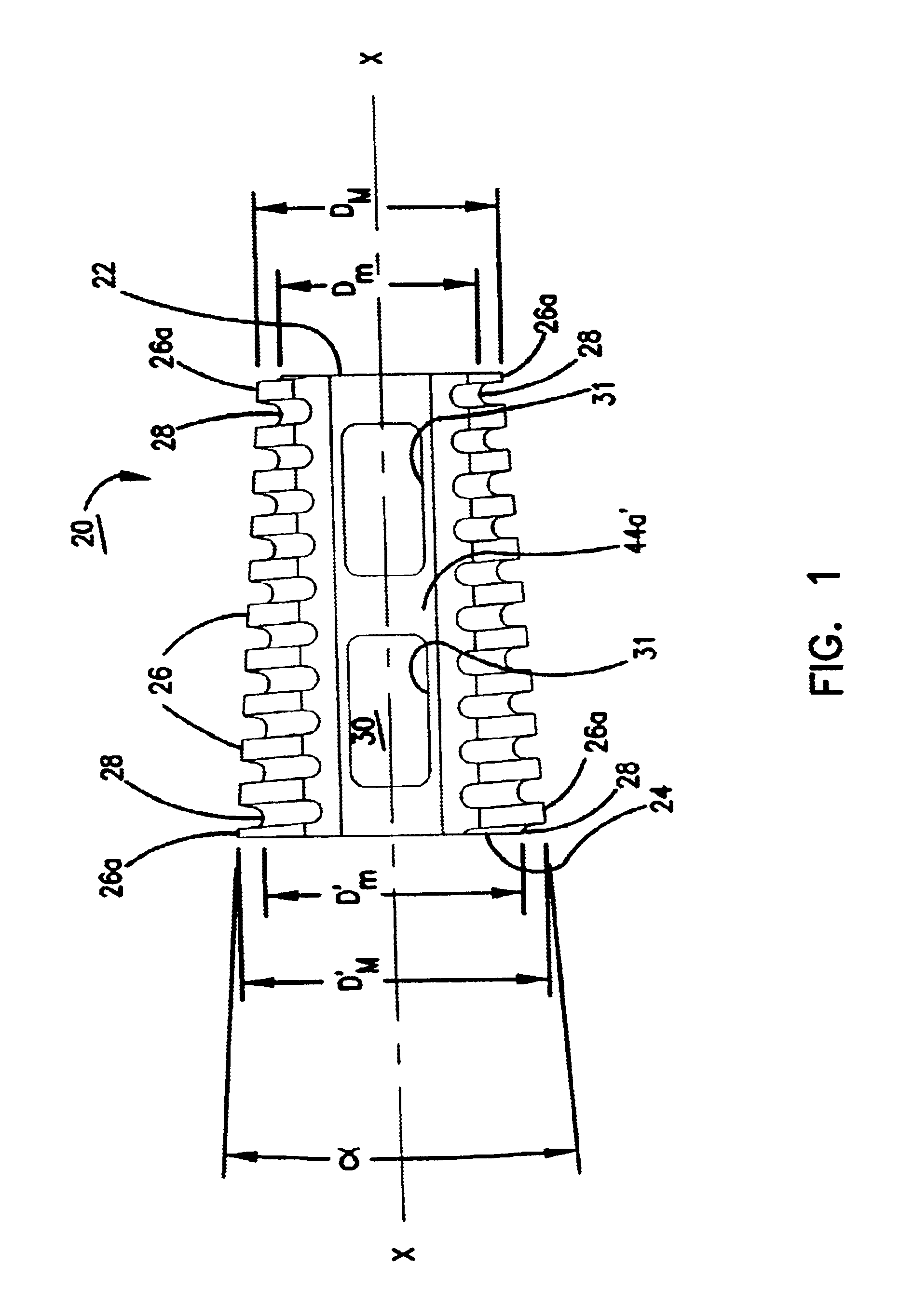
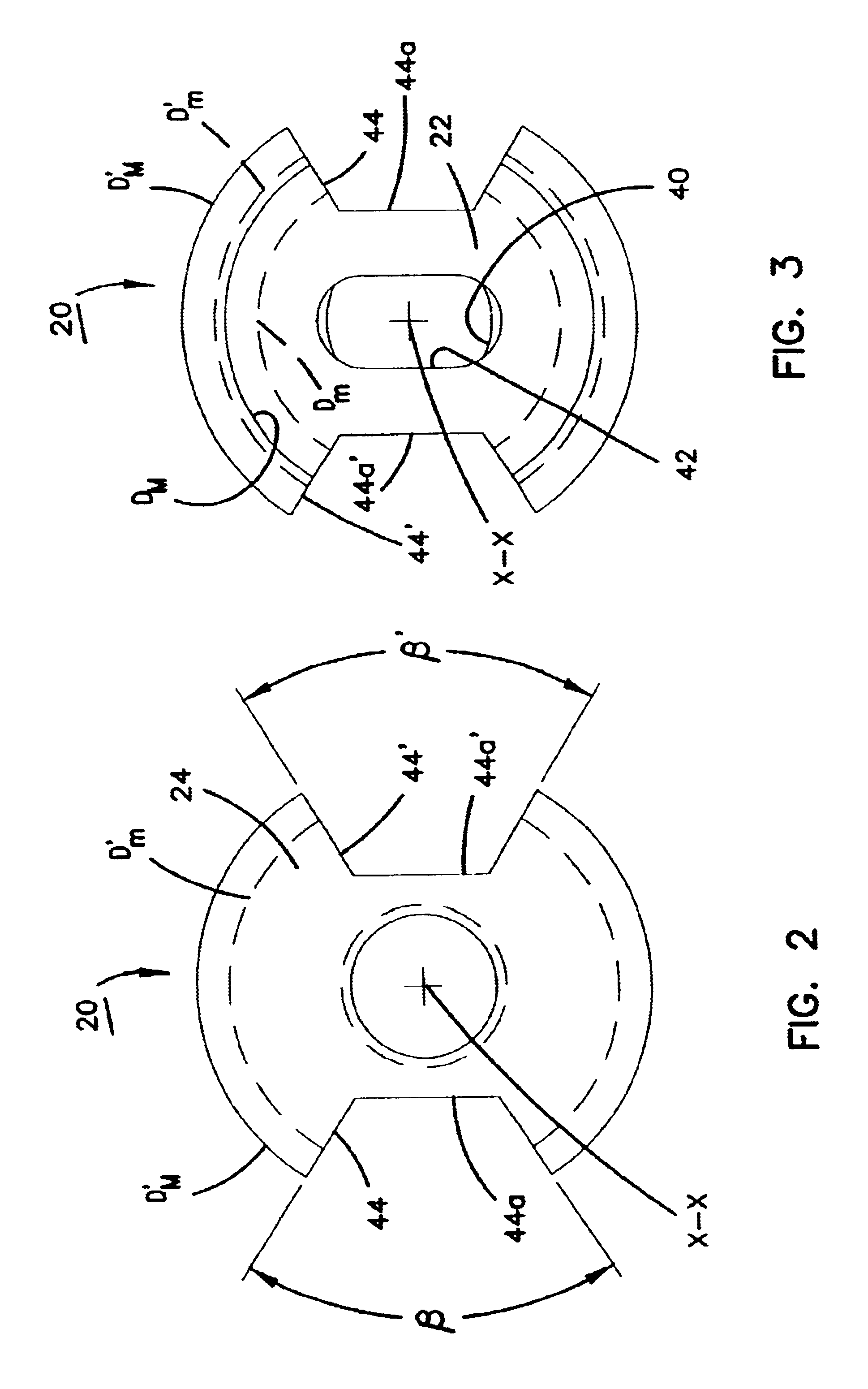
With reference now to the various drawing Figures in which identical elements are numbered identically throughout, a description of the preferred embodiment under the present invention will now be provided. As will become apparent, the present invention utilizes certain surgical methods and tools disclosed more fully in U.S. Pat. No. 5,489,307 incorporated herein by reference.

With initial reference to FIG. 18, a healthy spine is schematically shown to illustrate lordosis in the spine. As shown in the example of FIG. 18, the end plates 10.sub.2, 10.sub.3 of vertebrae L-2 and L-3 are in parallel alignment. Similarly, the end plates 10.sub.3 ' and 10.sub.4 of vertebrae L-3 and L-4 are in parallel alignment. However, the end plates 10.sub.4 ' and 10.sub.5 of vertebrae L-4 and L-5 are at a 3.degree. angle with the widest separation on the anterior, A, side of the spine and the narrowest separation on the posterior, P, side of the spine. Similarly, the end plates 10.sub.5 ' and 10.sub.1 o...


PUM

PropertyMeasurementUnit
angleaaaaaaaaaa
angleaaaaaaaaaa
anglesaaaaaaaaaa

Abstract

A lordotic implant has a frusto-conical shape with external threads. Prior to placement of the implant, vertebrae are distracted in a manner to provide a desired lordosis between the vertebrae. The pre-distracted vertebrae are then tapped to provide a tapped bore having a geometry matching the conical geometry of the implant. The threaded implant is then placed within the pre-tapped conical bore.

Description

I. BACKGROUND OF THE INVENTION1. Field of the InventionThis invention pertains to spinal implants and surgical procedures for use in spinal stabilization. More particularly, this invention pertains to an apparatus and method for implanting a tapered implant between two vertebrae.2. Description of the Prior ArtChronic back problems can cause pain and disability for a large segment of the population. In many cases, the chronic back problems are attributed to relative movement between vertebrae in the spine.Orthopedic surgery includes procedures to stabilize vertebrae. Common stabilization techniques include fusing the vertebrae together. Fusion techniques include removing disk material which separates the vertebrae and impacting bone into the disk area. The impacted bone fuses with the bone material in the vertebrae to thereby fuse the two vertebrae together.To increase the probability of a successful fusion, spinal implants have been developed. Commonly assigned U.S. Pat. No. 5,489,3...

Claims


Application Information

Patent Timeline
Patent Type & Authority Patents(United States)
IPC IPC(8): A61B17/16A61F2/44A61F2/46A61F2/30A61F2/28A61F2/00A61B17/56
CPCA61B17/1671A61F2/446A61F2/4611Y10T408/90467A61F2002/2835A61F2002/3021A61F2002/30217A61F2002/30774A61F2002/30777A61F2002/30785A61F2002/30797A61F2002/30868A61F2002/30874A61F2002/4475A61F2002/4627A61F2230/0067Y10S606/916Y10T408/896Y10T408/9046Y10T408/9048A61F2/442A61F2002/30873A61F2002/30593
Inventor KOHRS, DOUGLAS W.SAND, PAUL M.
Owner ZIMMER SPINE INC
Learn More