Eccentric gear

a gear and eccentric technology, applied in the direction of gearing, toothed gearing, belt/chain/gearing, etc., can solve the problems of increasing manufacturing difficulties, limiting the performance of gears, and previously known eccentric gears are associated with problems and shortcomings

Inactive Publication Date: 2004-06-01
EWELLIX AB
View PDF9 Cites 16 Cited by
  • Summary
  • Abstract
  • Description
  • Claims
  • Application Information

AI Technical Summary

Problems solved by technology

The previously known reduction gears of the eccentric type are, however, also associated with problems and shortcomings.
Among other things, a large number of teeth on the male and female gear rims of the gear is required at high gear changes, which entails that the teeth compulsorily become small; something which limits the performance of the gears and increases the manufacturing difficulties.
Another problem, common for a plurality of the previously known eccentric gears, is the so-called "transmitter"-function, i.e. the need for particular means to eliminate the eccentric motion between the eccentrically working gear rim and the output shaft of the gear.
Strength problems, friction losses and angle plays increasing with time do, however, characterize the constructions according to the last-mentioned patents, the means for eliminating the eccentric motion between the gear rim and the output shaft tending to limit the performance of the gears within given outer dimensions.
Furthermore, these means account for a considerable part of the total manufacturing cost of the gears.

Method used


Image

  • Eccentric gear
  • Eccentric gear
  • Eccentric gear

Examples


Embodiment Construction

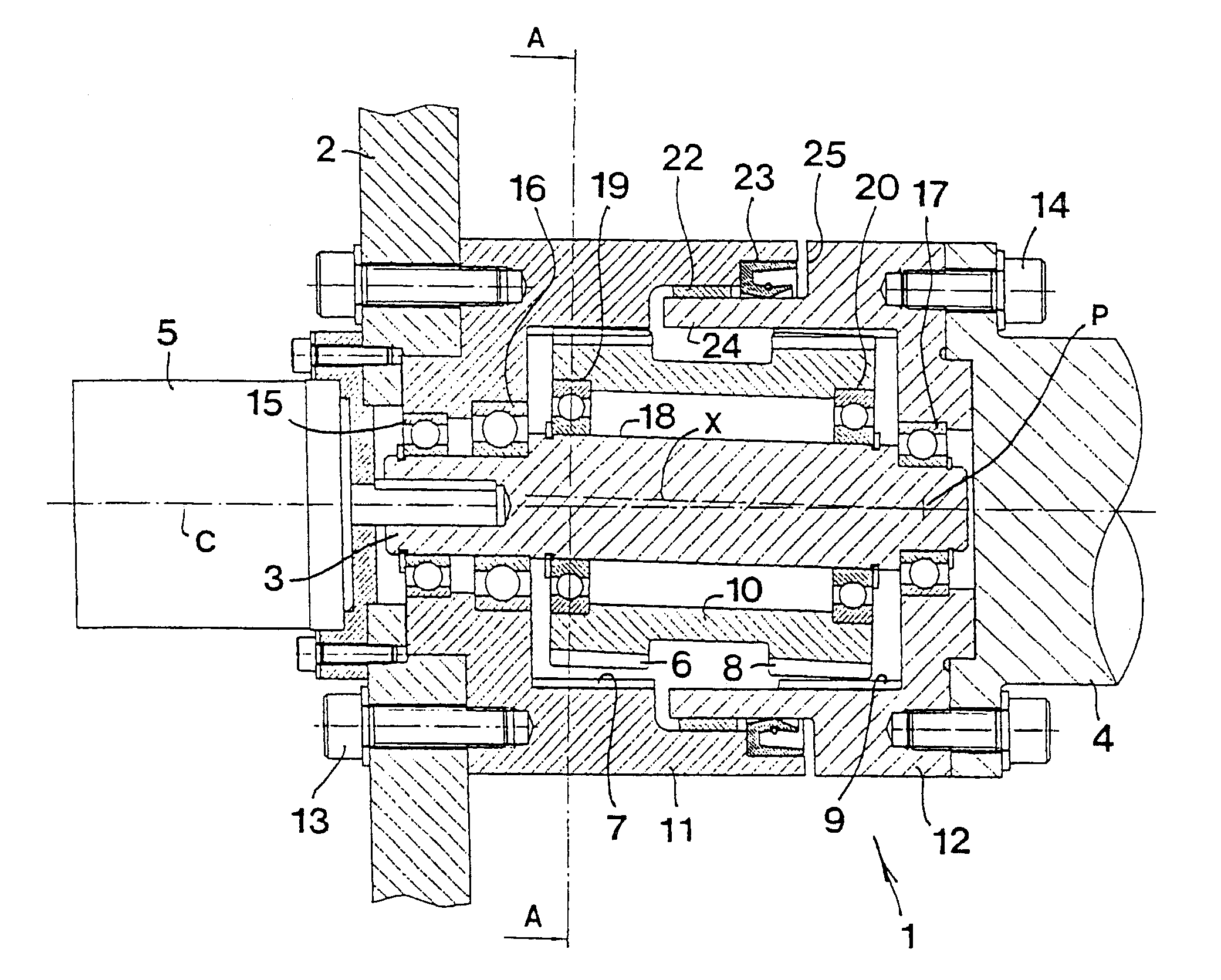
In FIG. 1, numeral 1 generally designates an eccentric gear made according to the invention, while numeral 2 designates a reference member in which the eccentric gear is mounted. In the example, the reference member 2 is assumed to consist of a spatially stationary included in a fixed machine stand. It should, however, already now be pointed out that the reference member 2 may in many practical applications also be rotatable. Furthermore, in FIG. 1, the reference numerals 3, 4 designate two rotatable machine elements, which in the example consist of shafts. More precisely, the element 3 consists of a short shaft piece, which is drivable from an external source of power 5, in the example consisting of a motor. However, also external sources of power are possible. In the gear, the shaft 3 constitutes an input or driving shaft, while the second shaft 4 is an output and driven shaft. The two shafts 3, 4 are rotatable around a common geometrical symmetry axis C. At the end (not shown) th...


PUM


Abstract

An eccentric gear for providing a speed difference between two machine elements which are rotatably journalled in relation to a reference member and individually rotatable around a symmetry axis. The gear includes two pairs of co-operating gear rims, one of which in each pair is eccentric in relation to the axis and one of which is in the form of a male gear rim with out-turned teeth, and the other one is a female gear rim with in-turned teeth. One of the gear rims in each pair is rigidly connected to a homologous gear rim in the other pair of gear rims and situated along a common axis that is eccentric and oblique in relation to the axis while the other gear rims are rotatable in relation to each other.

Description

TECHNICAL OF THE INVENTIONThis invention relates to an eccentric gear for providing a speed difference between two machine elements which are rotatably mounted in relation to a reference member and individually rotatable around a common geometrical symmetry axis, including a pair of co-operating gear rims, one of which is eccentric in relation to the symmetry axis and one of which is in the form of a male-like gear rim formed with out-turned teeth, and the other one is in the form of a female-like gear rim which is formed with in-turned teeth and has a larger diameter than the male gear rim in order to enable engagement of only one or a few of the teeth of the male gear rim in the female gear rim, one of the gear rims being arranged to roll off against the other one.Prior ArtIn comparison to planetary gears, eccentric gears have a plurality of fundamental advantages. Eccentric gears enable, above all, a high gear change in one single step, at the same time as the same have servo-tec...

Claims


Application Information

Patent Timeline
Patent Type & Authority Patents(United States)
IPC IPC(8): F16H1/32
CPCF16H1/321
Inventor RILBE, ULF
Owner EWELLIX AB
Why Eureka
Try Eureka