Annual date mechanism for clock movement

a date mechanism and clock movement technology, applied in mechanical clocks, instruments, horology, etc., can solve the problems of relatively complicated mechanisms of the above mentioned, and achieve the effect of small bulk and reliable operation

Inactive Publication Date: 2004-06-01
ROLEX SA
View PDF9 Cites 31 Cited by
  • Summary
  • Abstract
  • Description
  • Claims
  • Application Information

AI Technical Summary

Benefits of technology

The object of the present invention is to render annual a simple date mechanism, preferably instantaneous, using

Problems solved by technology

Furthermore, some of the aforementioned

Method used


Image

  • Annual date mechanism for clock movement
  • Annual date mechanism for clock movement
  • Annual date mechanism for clock movement

Examples


Embodiment Construction

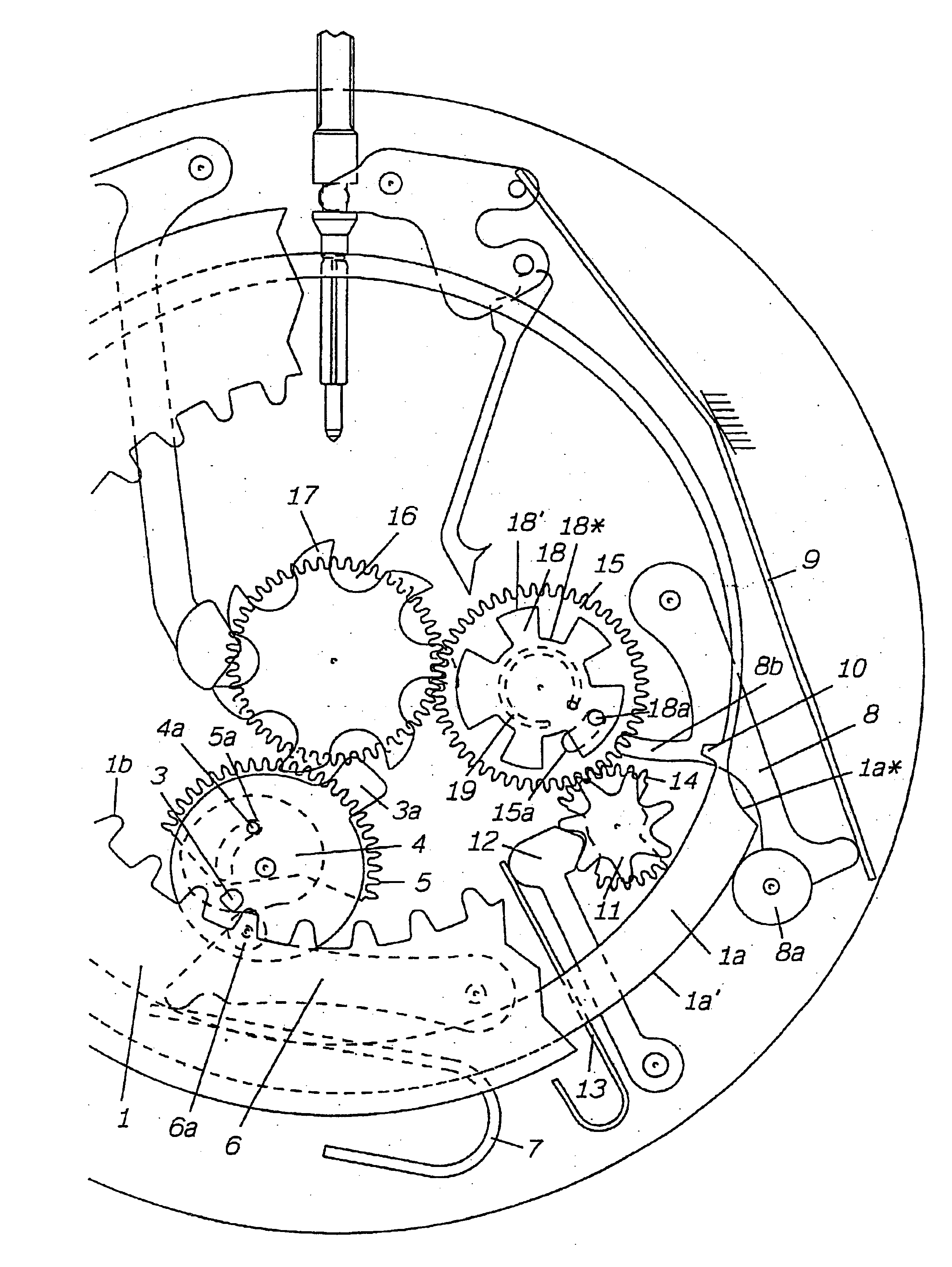
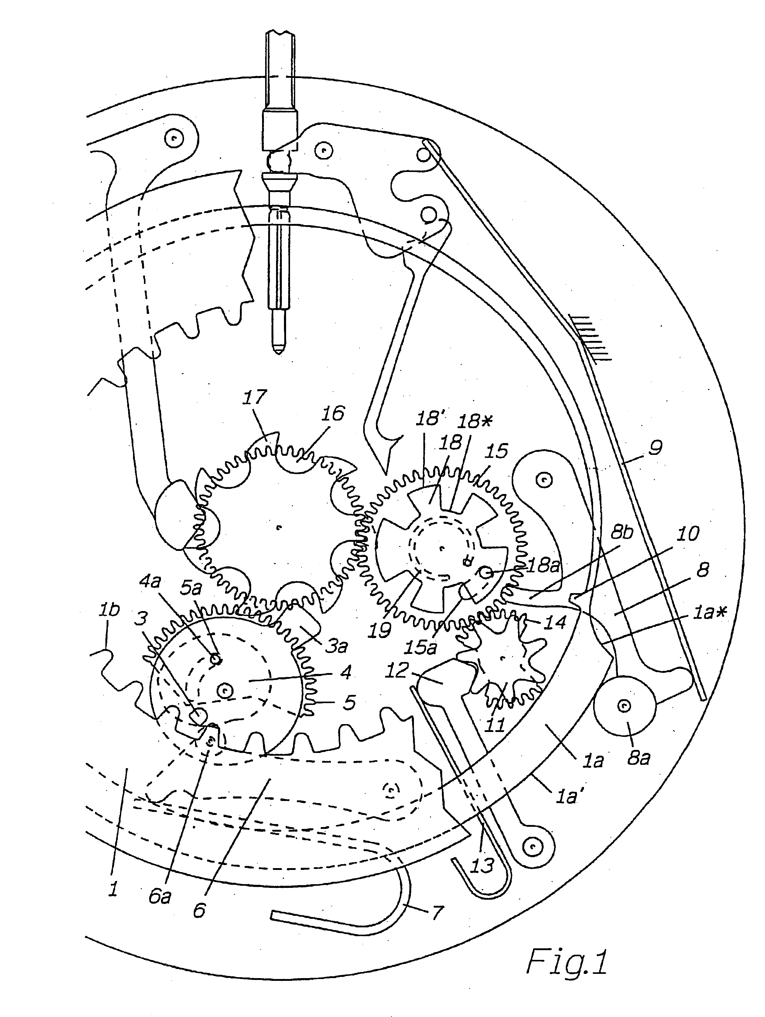
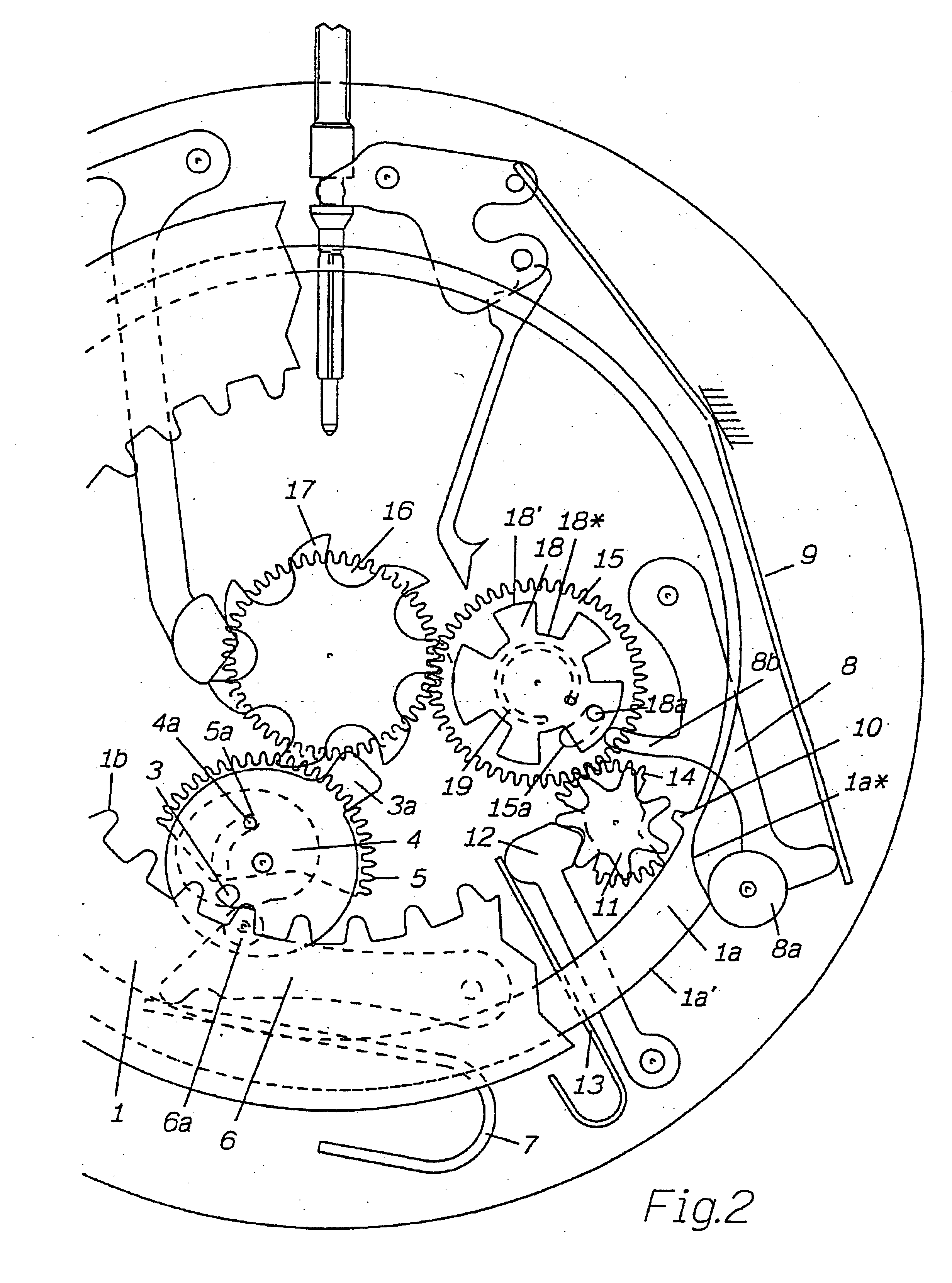
The date mechanism illustrated by FIGS. 1 to 5 comprises an annular runner 1 bearing the dates from 1 to 31. This annular runner 1, more generally known as the date disk, has the customary internal set of teeth 1b and is secured to an annular correction cam 1a.

The set of teeth 1b is engaged, on the one hand, with a position jumper 2 (FIG. 6) and, on the other hand, with a driving finger 3 secured to an instantaneous jump cam 4 concentric with a driving wheel 5. An opening in the shape of a circular arc 5a secured to the driving wheel 5 and a pin 4a secured to the instantaneous jump cam 4 serve to secure this cam to the driving wheel but also allow a certain angular play the purpose of which will be explained later on. A roller 6a of a rocker 6 for the instantaneous changing of the date is pressed against the periphery of the instantaneous jump cam 4 by a spring 7.

In this embodiment, a second finger 3a is intended to drive a seven-branched days-of-the-week star 17 once per day at the...


PUM


Abstract

This annual date mechanism comprises a correction cam (1a) in kinematic connection with a date indicating runner (1), a correction rocker (8) engaged on the one hand with said correction cam (1a) and, on the other hand, with an annual cam (18). A spring (9) presses the correction rocker (8) against the cams (1a, 18). The correction cam (1a) comprises a portion (1a') for arming said spring (9), followed by a portion (1a*) sized to cause said date runner (1) to move by one step between "31" and "1", under the pressure of said spring (9).

Description

CROSS REFERENCE TO THE RELATED APPLICATIONSThis application claims priority of European Application No. 02405094.0 filed Feb. 11, 2002, entitled Annual Date Mechanism for Clock Movement.1. Field of the InventionThe present invention relates to an annual date mechanism for a clock movement comprising a date indicating runner with thirty-one positions engaged once a day with a drive runner in kinematic connection with the geartrain of said clock movement, an annual cam, the contour of which is shaped to distinguish the thirty-one-day months from the other months, means for driving this cam by one revolution per year and a correction mechanism connected to said annual cam to advance said indicating runner by one additional position at the end of each month of less than 31 days.This type of date mechanism which is a compromise between the simple date and the perpetual or semi-perpetual date involving a relatively complicated and therefore tricky mechanism made up of a fairly large numbe...

Claims


Application Information

Patent Timeline
IPC IPC(8): G04B19/253G04B19/00
CPCG04B19/2536
Inventor VERNAY, FRANKGRAEMIGER, PIERRE-ALAIN
Owner ROLEX SA
Why Eureka
Try Eureka