Winding method and winding device

a winding device and winding technology, applied in windings, dynamo-electric components, inductance/transformers/magnets, etc., can solve the problems of inability to apply the method to the distributed winding in which wires are wound over a plurality of teeth, inability to be wound, and inability to increase the density of the wire cor

Inactive Publication Date: 2004-06-15
NITTOKU ENG CO LTD
View PDF15 Cites 35 Cited by
  • Summary
  • Abstract
  • Description
  • Claims
  • Application Information

AI Technical Summary

Benefits of technology

Furthermore, the size and cost of the winding device can be reduced in comparison with a conventional inserter winding method.

Problems solved by technology

However, although the direct winding methods (a) and (b) are applied to concentrated winding in which wires are wound in concentration onto each tooth, these methods cannot be applied to distributed winding in which wires are wound over a plurality of teeth.
If an attempt is made to perform distributed winding using the direct winding methods in (a) and (b), the wire of the initially wound phase over the slot causes an obstruction such that the wire to be wound in the following phases cannot be wound.
Even if the wires are inserted into the slots by manual labor, a gap appears between the core and the wire, with the result that the wire space factor (density) in respect of the core cannot be increased.
However, the coil end portion of the winding increases in length, leading to an increase in the size of the coil and the necessity for a procedure to shape the coil end portion.
Moreover, even if the coil end portion does not affect the torque generated by the motor, when the coil end portion increases in length, the amount of heat generation increases due to copper loss.

Method used


Image

  • Winding method and winding device
  • Winding method and winding device
  • Winding method and winding device

Examples


second embodiment

A second embodiment illustrated in FIGS. 13 to 15 will now be described. Note that identical components to the first embodiment are allocated identical reference numerals. The first and second embodiments are identical except for the nozzle 3 and the former 81.

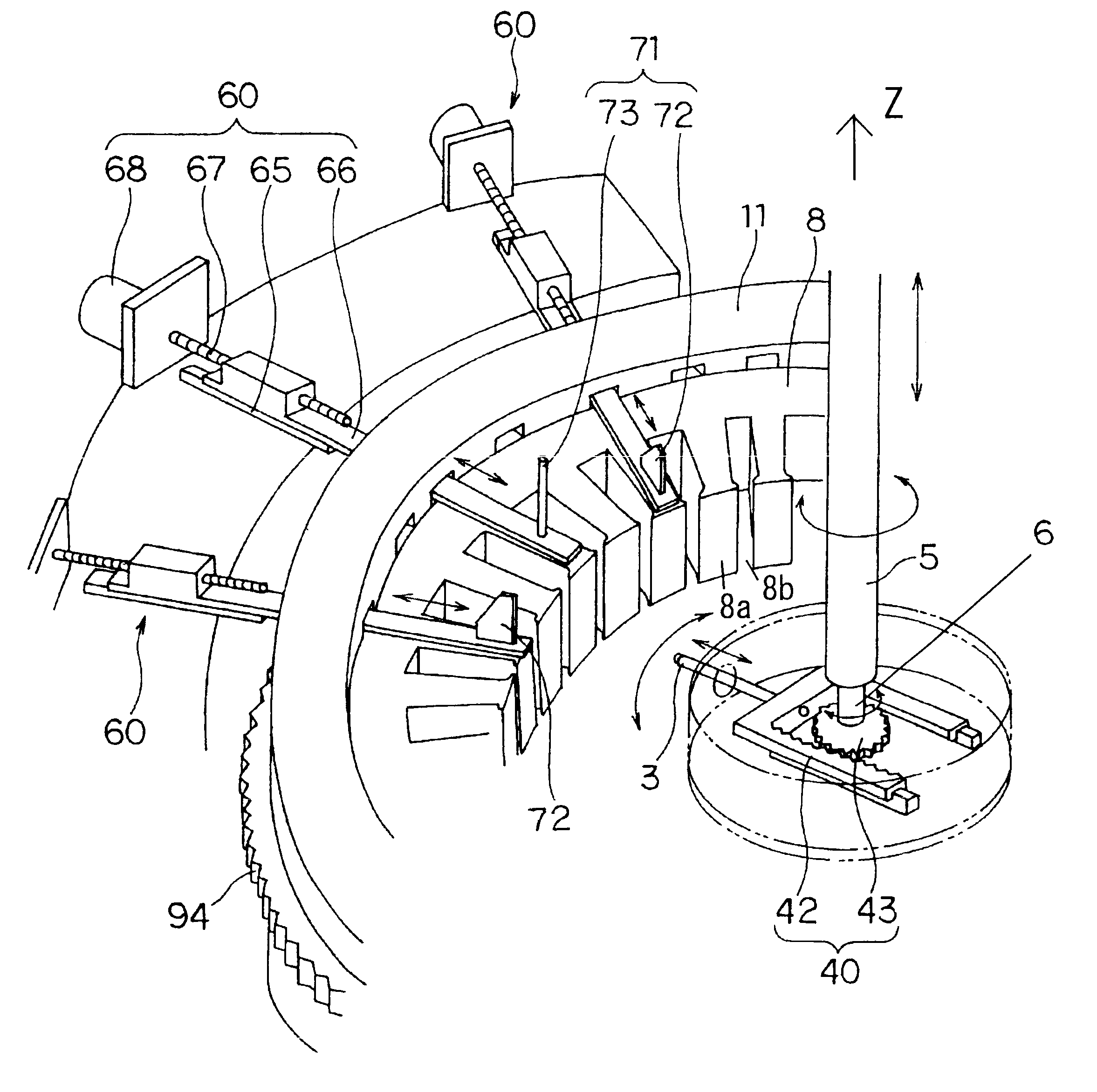
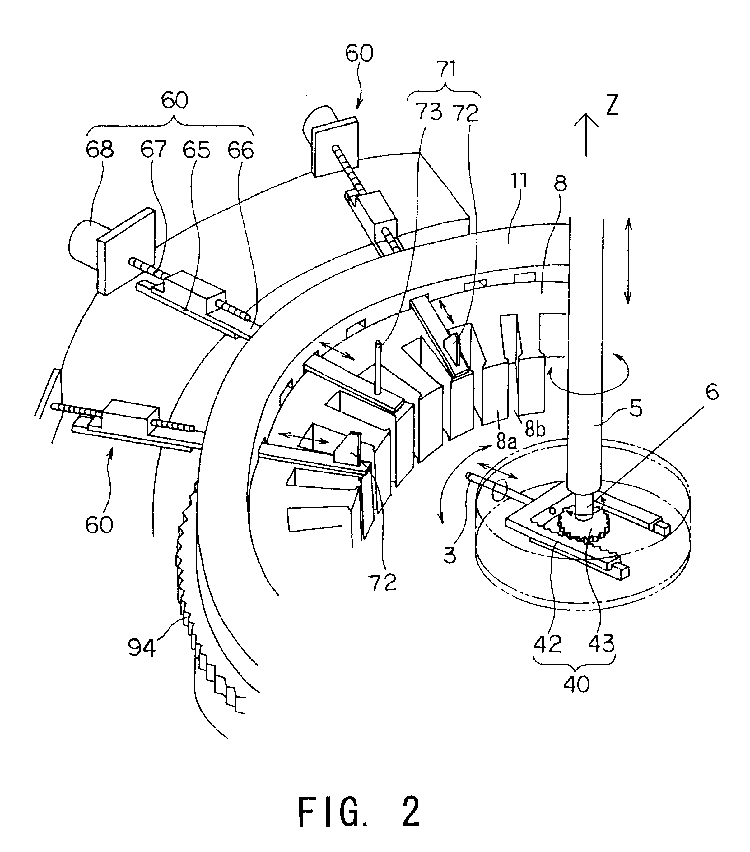
The nozzle 3 is provided with two control plates 34 for letting out a plurality of wires 90 aligned lengthways. The control plates 34 are inserted into a slot 8b, whereby the wires 90 are wound around the teeth 8a.

The nozzle 3 comprises a square frame-shaped main body 35 through which the plurality of wires 90 pass lengthways and in alignment, and the control plates 34 are fixed in parallel inside this main body 35 so as to sandwich the wires 90.

A pair of rollers 36 is attached to the upper and lower portions of the main body 35. By rotating against the upper and lower end wires 90 respectively, the rollers 36 allow each wire 90 to be let out from the nozzle 3 smoothly.

Further the rollers 36 are disposed near the upper and low...


PUM

PropertyMeasurementUnit
concentrationaaaaaaaaaa
densityaaaaaaaaaa
lengthaaaaaaaaaa

Abstract

A winding device winds a wire (90) onto a core (8) having a plurality of teeth (8b) protruding from a yoke and having slots (8a) formed between each tooth (8b). The winding device winds the wire (90) by causing a nozzle (3) which lets out the wire (90) to perform a relative motion. The winding device is provided with pusher plates (72) which guide the wire (90) into the slots (8a), and inserts the wire (90) into the slots (8a) by causing the pusher plates (72) to move relative to the core (8).

Description

This invention relates to improvements in a winding method and winding device for winding a wire around the stator core of an electric motor or a generator.DESCRIPTION OF THE RELATED ARTAs conventional winding methods applied to an inner rotor type stator, a direct winding method in which a wire is directly wound onto teeth, and an inserter winding method in which a pre-wound wire is inserted into a slot are known. The following methods described in (a) and (b) are direct winding methods.(a) A direct winding method in which a wire is wound onto a core by inserting a nozzle which supplies the wire into the interior of each slot.(b) A direct winding method in which a wire is wound onto a core by moving the nozzle which supplies the wire on the outside of each slot.The following method described in (c) is an inserter winding method.(c) An inserter winding method in which a wire is wound in advance onto a rod-shaped member disposed along the inside of teeth, whereupon the wire is insert...

Claims


Application Information

Patent Timeline
Patent Type & Authority Patents(United States)
IPC IPC(8): H02K15/08H02K15/085H02K15/06
CPCH02K15/085H02K15/06Y10T29/49009H02K3/46
Inventor KOMURO, KATSUROUIGARASHI, ITARU
Owner NITTOKU ENG CO LTD
Why Eureka
Try Eureka