System and method for measuring oil condition in large engines

a technology for oil condition measurement and engines, applied in the direction of auxilary lubrication, crankcase compression engine lubrication, instruments, etc., can solve the problems of oil waste, engine damage, waste of oil,

Inactive Publication Date: 2004-06-15
DELPHI TECH INC
View PDF7 Cites 17 Cited by
  • Summary
  • Abstract
  • Description
  • Claims
  • Application Information

AI Technical Summary

Problems solved by technology

If too long a period elapses between maintenance, an engine can be damaged.
On the other hand, conducting maintenance when it is not needed is wasteful both in terms of labor and in terms of natural resources.
For example, if an engine doesn't require an oil change but nevertheless receives one, oil is in effect wasted.
Unfortunately, many larger industrial engines, e.g., large diesel generators and heavy equipment engines, do not include any means for sensing the condition of the lubricating oil.
As such, retrofitting an existing engine to include an oil condition sensor can be very cost prohibitive.

Method used


Image

  • System and method for measuring oil condition in large engines
  • System and method for measuring oil condition in large engines

Examples


Embodiment Construction

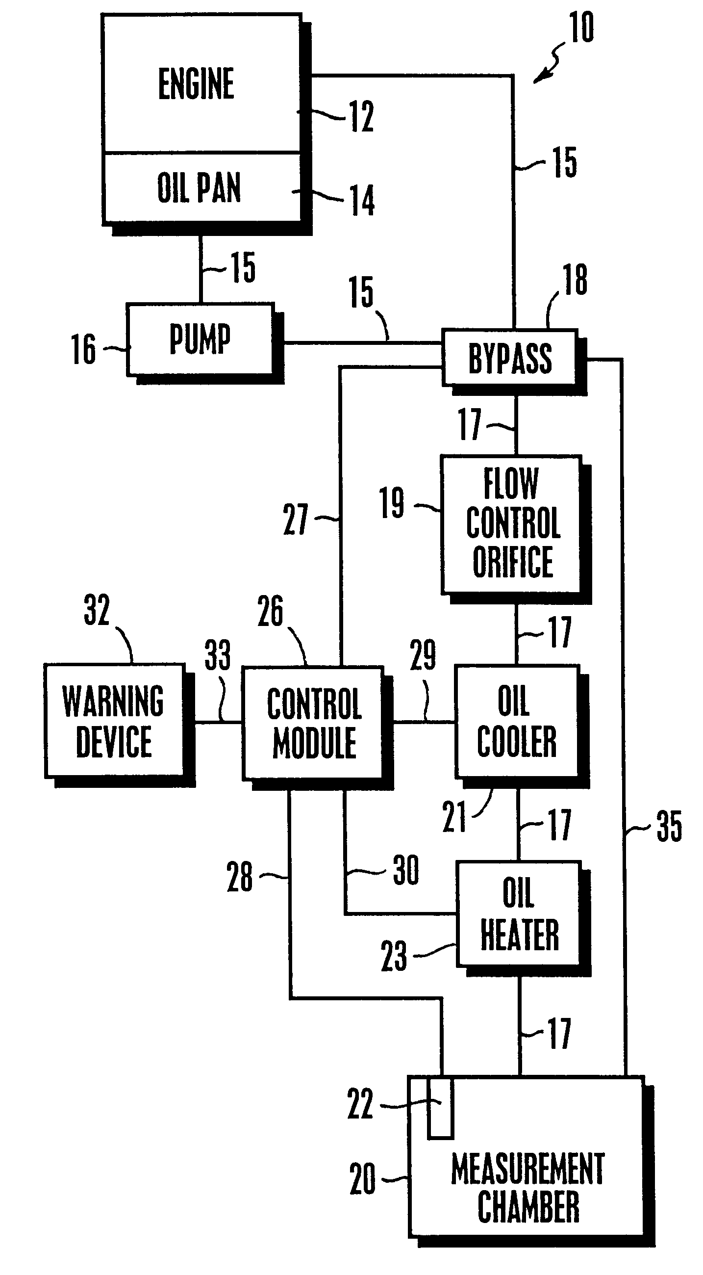
Referring initially to FIG. 1, a vehicle lubrication system is shown and generally designated 10. FIG. 1 shows that the lubrication system includes an engine 12 and an oil reservoir, e.g., an oil pan 14, in fluid communication with the engine 12 via fluid line 15. As shown in FIG. 1, an oil pump 16 is installed along fluid line 15 so that it is in fluid communication with the engine 12 and the oil pan 14. The oil pump 16 pumps oil from the oil pan 14 to the engine 12 in order to lubricate moving parts within the engine 12, e.g., the rocker arms, and cam shafts.

FIG. 1 shows a bypass valve 18 installed between the pump 16 and the engine 12. When energized, the bypass valve 18 allows oil in the lubrication system 10 to pass into a measurement chamber 20 in which an oil condition sensor 22 is installed. It is to be appreciated that the oil condition sensor 22 is, e.g., a standard oil condition sensor that is found on many light vehicles. Thus, oil can be bypassed from the lubrication sy...


PUM

PropertyMeasurementUnit
temperatureaaaaaaaaaa
structureaaaaaaaaaa
structuresaaaaaaaaaa

Abstract

A system for measuring oil condition in large engines includes a bypass valve that is installed in a lubrication system along a fluid line between an oil pan and an engine. The bypass valve communicates with a measurement chamber and when energized by a control module, the bypass valve diverts oil from the lubrication system to the measurement chamber. An oil condition sensor is disposed within the measurement chamber and is used to determine the condition of the oil that is diverted to the chamber. After the condition of the oil is determined, the bypass valve is energized to release the oil from the measurement chamber back into the lubrication system.

Description

1. Technical FieldThe present invention relates generally to oil condition sensors.2. Background of the InventionAutomatically monitoring the quality of oil in an engine alerts owners in a timely fashion when maintenance should be performed as dictated by the actual condition of the oil. Performing maintenance when it is actually required is preferred over following a predetermined, one-size-fits-all schedule that might be too long or too short for any given vehicle, depending on the way the vehicle is driven. If too long a period elapses between maintenance, an engine can be damaged. On the other hand, conducting maintenance when it is not needed is wasteful both in terms of labor and in terms of natural resources. For example, if an engine doesn't require an oil change but nevertheless receives one, oil is in effect wasted.Accordingly, oil condition sensors have been provided for small engines, e.g., motor vehicle engines, that measure various parameters of lubricating oil, and to...

Claims


Application Information

Patent Timeline
Patent Type & Authority Patents(United States)
IPC IPC(8): G01N33/26G01N33/28
CPCG01N33/2888
Inventor ISMAIL, KEITH N.LECEA, OSCAR ALFONSOTHOMSON, STEVEN DOUGLAS
Owner DELPHI TECH INC
Why Eureka
Try Eureka