Spinner unit

a spinner and unit technology, applied in the field of spinner units, can solve the problems of large amounts of feed falling under the feeder, inability of many spinner plates to maximize the distance the feed travels from the feeder, and thieving birds and small animals

Inactive Publication Date: 2004-07-20
NORRELL JAMES EDWARD
View PDF24 Cites 28 Cited by
  • Summary
  • Abstract
  • Description
  • Claims
  • Application Information

AI Technical Summary

Problems solved by technology

Thieving birds and small animals have plagued feeder operators for years.
Another operator problem is the inability of the spinner plate to prevent feed from being thrown upwardly from the spinner plate as it spins, leaving substantial amounts of feed to fall beneath the feeder instead of being thrown clear of the feeder to an area of some distance from the feeder.
A related problem is the inability of many spinner plates to maximize the distance the feed travels from the feeder, and to throw the feed in a consistent and uniform manner in a circular area about the feeder.
Feed dislodged in this manner lands beneath, or much too close to the feeder, resulting in substantial loss of feed, to the point that the feed storage unit can be emptied by the continued discharge of feed onto a spinner plate cleared by the wind.
Feeders are often left unattended for extended periods of time, and this problem can cause a feeder to be emptied and useless for long periods of time.
The Reneau device also has no structure for enhancing the consistency and uniformity of the feed distribution, instead having a wide, gated mouth.
The Reneau gates are also subject to being flipped backward over the top of the spinner plate, leaving feed exposed at the openings.
Similarly, U.S. Pat. No. 5,143,289 to Gresham, et al. allows unnecessarily easy small animal access due to the lack of a covering top and sides, above and around, significant portions of the feed.
Also, little or no access through the housing discharge openings is available to such animals.

Method used


Image

  • Spinner unit
  • Spinner unit
  • Spinner unit

Examples


Embodiment Construction

The following discussion describes in detail exemplary embodiments of the invention. This discussion should not be construed, however, as limiting the invention to those particular embodiments. Practitioners skilled in the art will recognize numerous other embodiments as well. For a definition of the complete scope of the invention, the reader is directed to the appended claims.

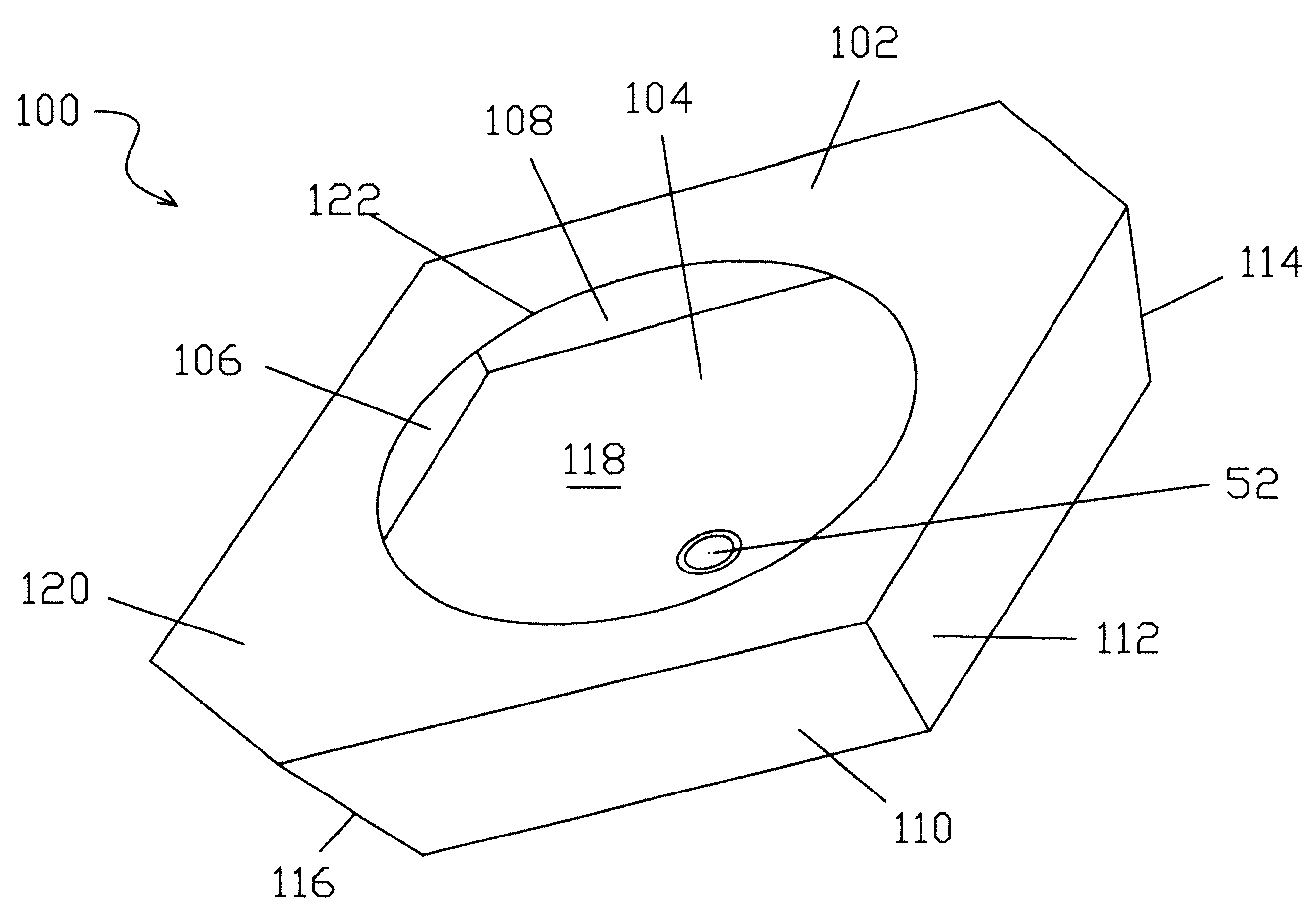
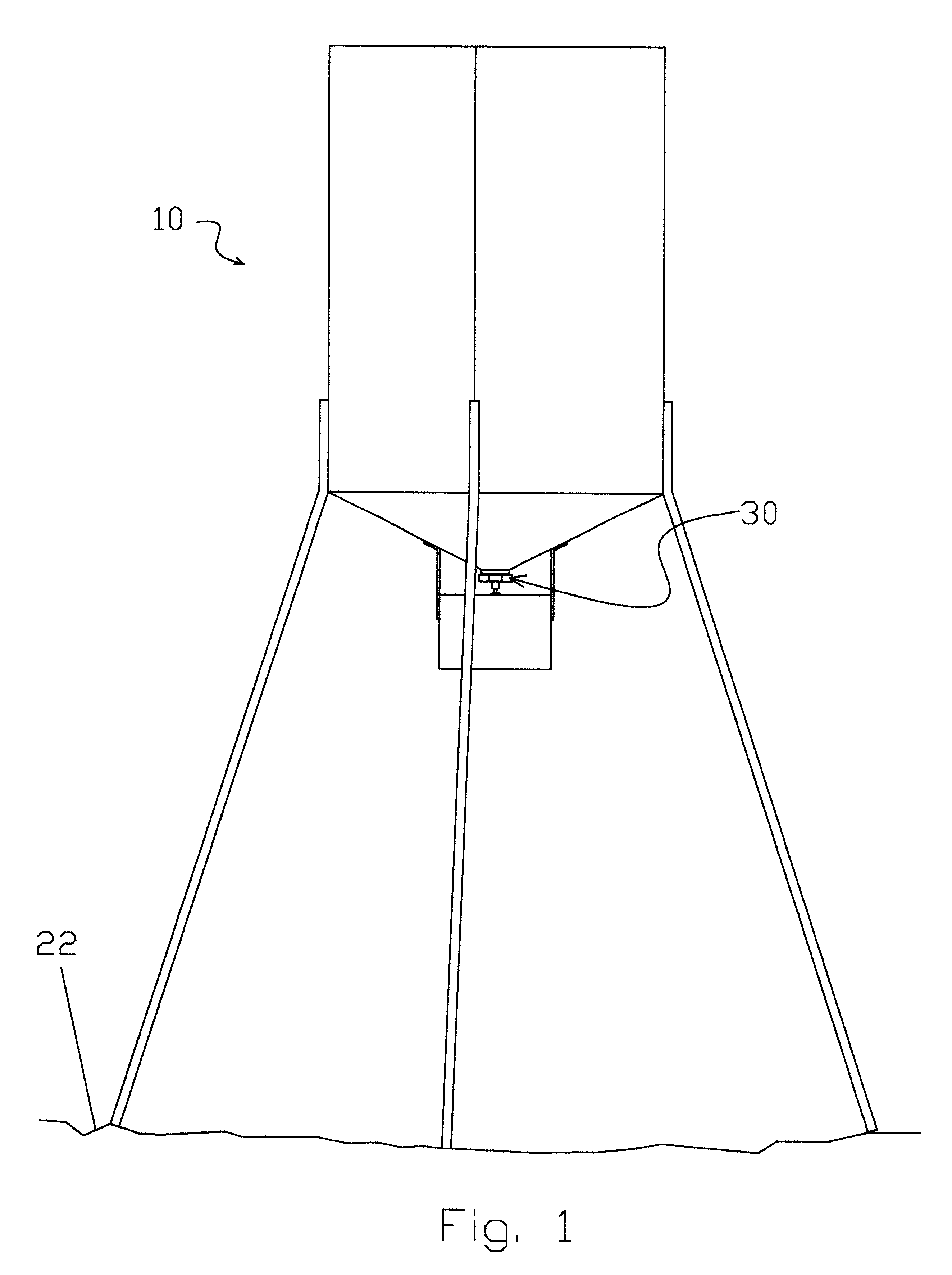
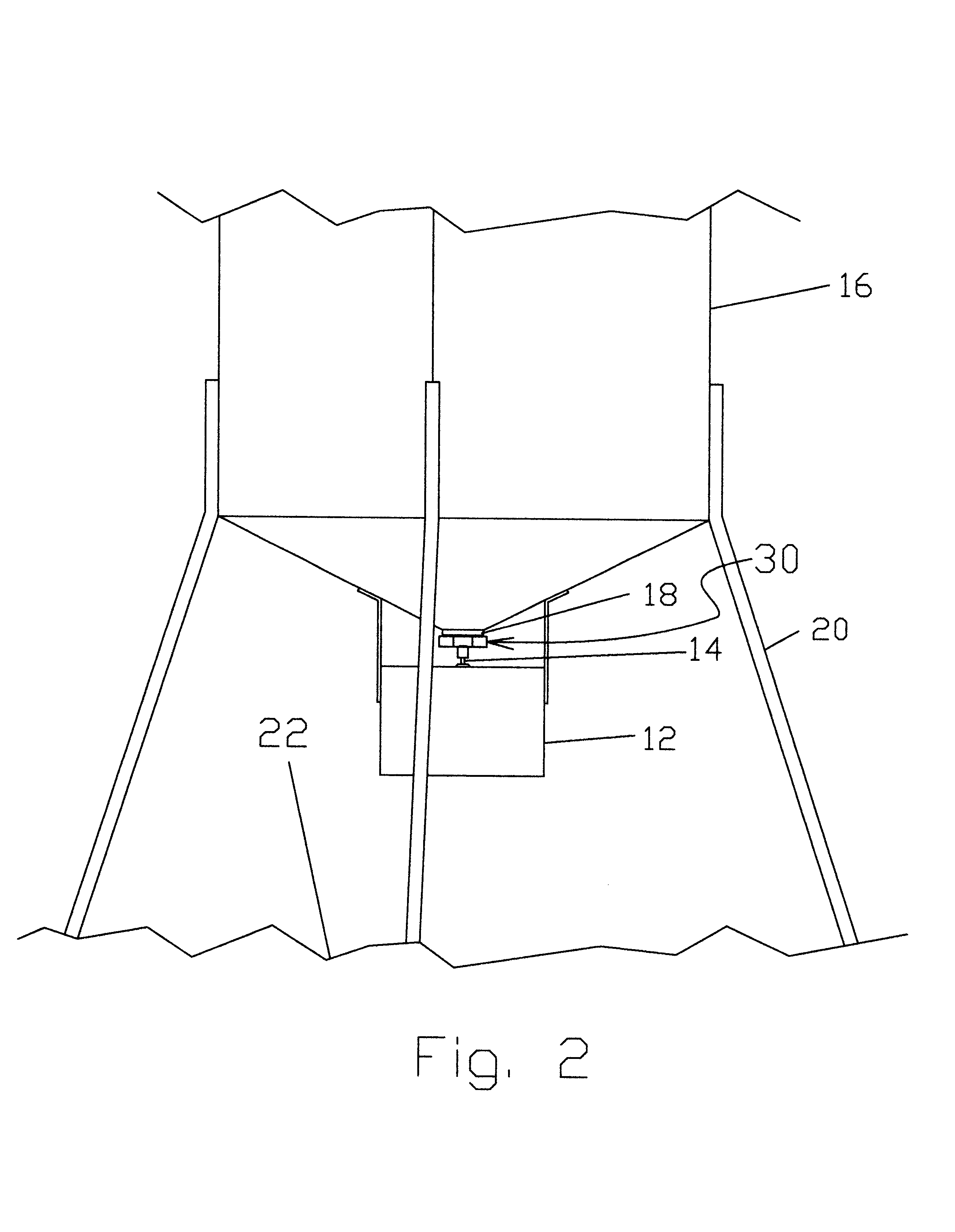
An exemplary embodiment of a spinner unit 30 of the present invention is illustrated in FIGS. 1-5. In FIGS. 1-2, the exemplary spinner unit 30 is shown in use on a typical animal feeder 10 of the type having a battery-powered, motorized control unit 12, having an upwardly directed shaft 14 to which the spinner unit 30 is attached. The control unit 12 is attached to feeder structure including a feed storage unit 16, the feed storage unit containing animal feed that exits through a feed storage unit discharge member 18. The discharge member 18 is typically tube-shaped and extends downwardly from the feed storag...


PUM


Abstract

My invention provides a spinner unit for attachment to the intermittently rotating vertical control unit shaft of an animal feeder, the feeder having a feed storage unit that discharges feed through a discharge tube into a spinner unit housing interior, where the feed is enclosed prior to discharge from specially configured discharge openings. The extensive covering configuration provided by the housing top, bottom and in some embodiments, sides, allows little or no feed to be thieved by small animals such as birds, prevents feed loss from wind, and prevents feed from being thrown up and off the spinner unit when the spinner unit is spinning.

Description

1. Field of the InventionThe field of the invention is animal and wildlife feeders, or, more specifically, enclosed spinner units for replacing spinner plates used for distributing feed from the feeders.2. Description of Related ArtIn the current art of animal and wildlife feeders, it is typical for the feeder to have a motorized control unit that intermittently rotates a vertically oriented shaft to which is attached a spinner plate. The spinner plate is positioned beneath a feed storage unit, the storage unit allowing feed, such as corn, to discharge through a tube directed onto the spinner plate. The spinner plate is typically rotated for about 8 seconds, twice a day, leaving the spinner plate stationary for long periods of time with a full load of feed from the feed storage unit. When the control unit shaft rotates the spinner plate the feed is thrown from the plate, in response to the centrifugal forces generated by the rapid spinning of the spinner plate.Thieving birds and sma...

Claims


Application Information

Patent Timeline
Patent Type & Authority Patents(United States)
IPC IPC(8): A01K5/02A01K39/01A01K39/00A01K5/00
CPCA01K5/02A01K39/0113
Inventor NORRELL, JAMES EDWARD
Owner NORRELL JAMES EDWARD
Why Eureka
Try Eureka