Structure for a vehicle seat element, and a method of making such a structure

a vehicle seat and structure technology, applied in the field of rigid structure, can solve the problems of the connection between the bushing and the composite fibers breaking when the hinge is opened, increasing the time required to assemble the seat, and increasing the manufacturing cos

a vehicle seat and structure technology, applied in the field of rigid structure, can solve the problems of the connection between the bushing and the composite fibers breaking when the hinge is opened, increasing the time required to assemble the seat, and increasing the manufacturing cos

US6767067B2Inactive Publication Date: 2004-07-27FAURECIA

Image

  • Structure for a vehicle seat element, and a method of making such a structure
  • Structure for a vehicle seat element, and a method of making such a structure
  • Structure for a vehicle seat element, and a method of making such a structure

Examples


Embodiment Construction

In the various figures, the same references designate elements that are identical or similar.

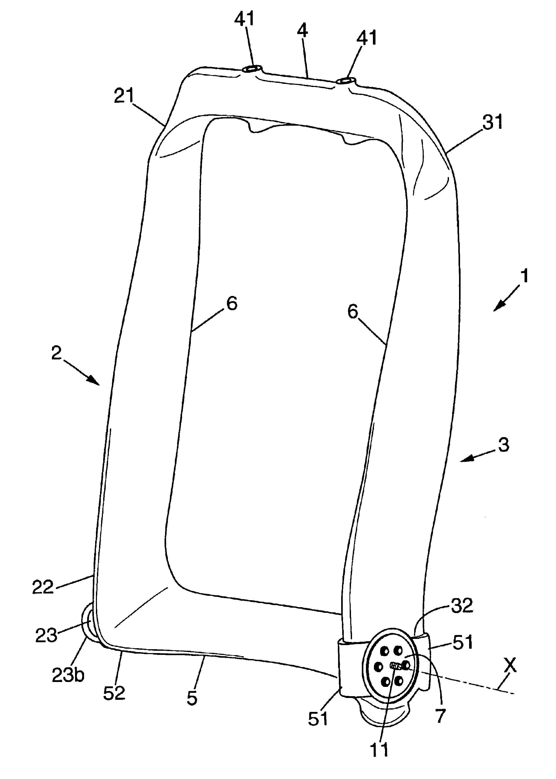
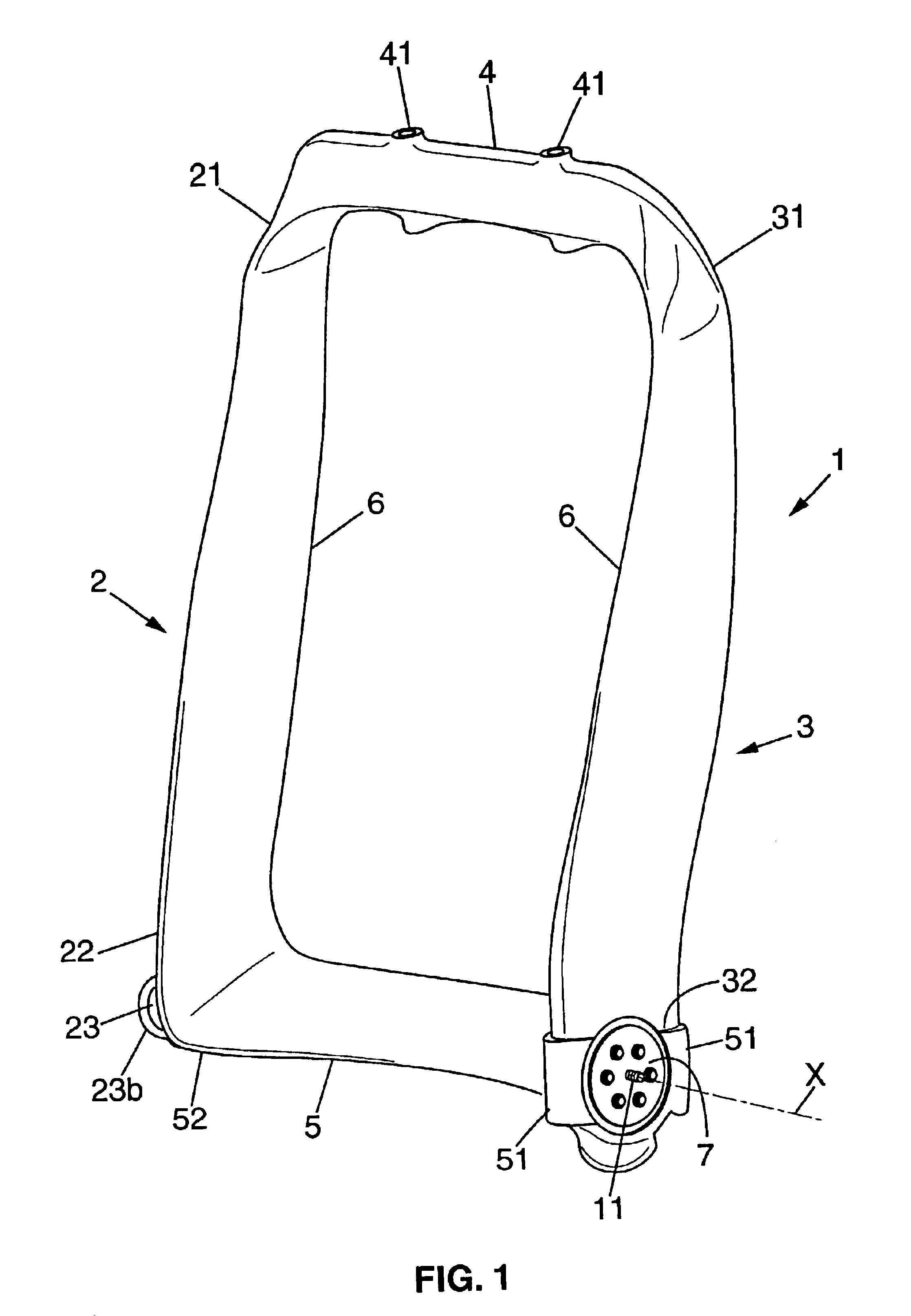
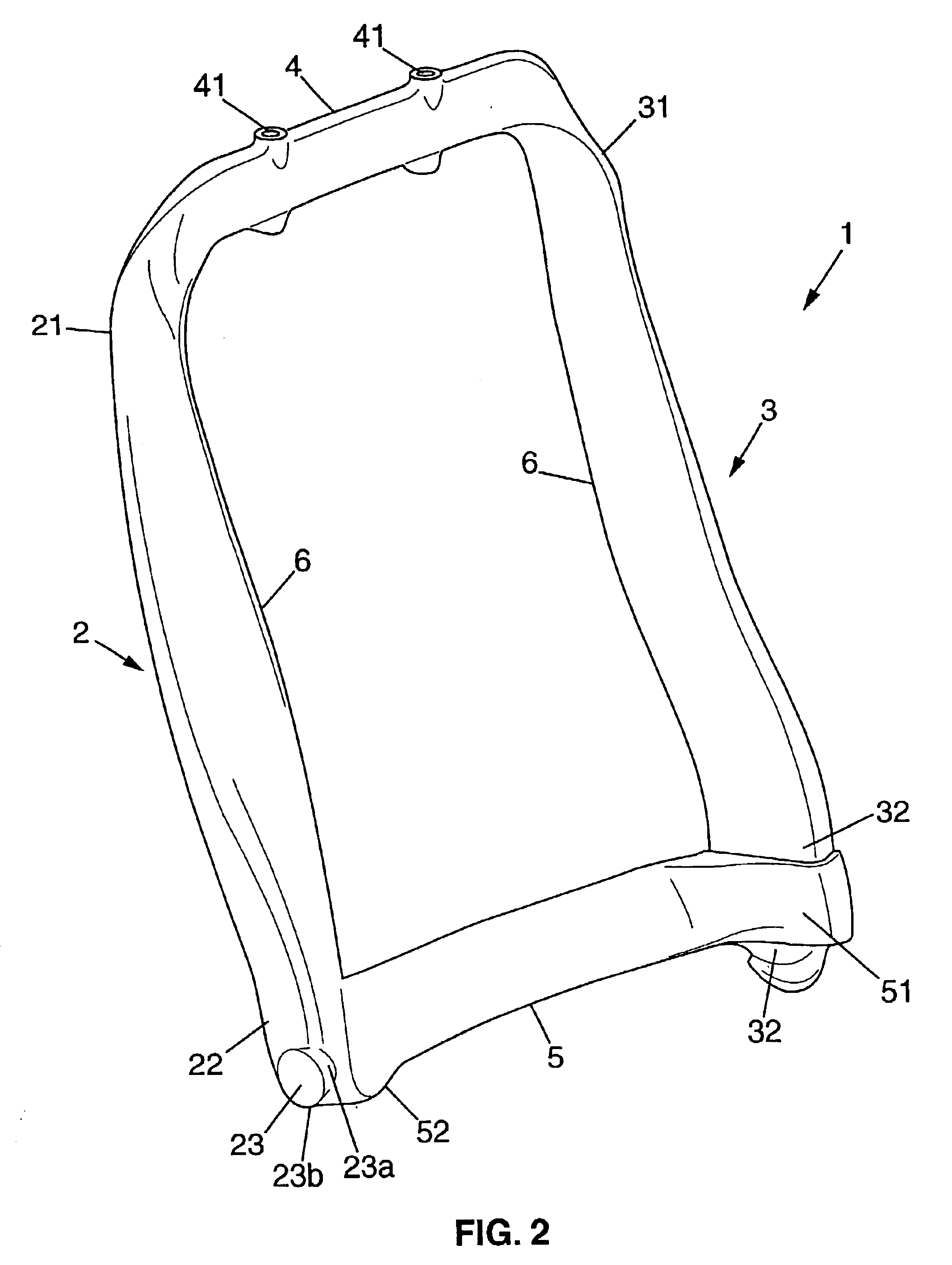
The rigid structure of a seat element shown in FIGS. 1 and 2 is constituted by a rigid structure for a seat back 1 comprising first and second sideplates or side uprights 2 and 3, each of which extends between a first end 22, 32 and a second end 21, 31. In this embodiment of a seat back structure, the first ends 22 and 32 of the side uprights 2 and 3 correspond to bottom ends, while the second ends 21 and 31 correspond to top ends of said uprights 2, 3. The seat back structure also comprises a top horizontal cross-member 4 which interconnects the top ends 21 and 31 of the side uprights 2 and 3, and a bottom horizontal cross-member 5 which interconnects the bottom ends 22 and 32 of said side uprights 2 and 3.

The two side uprights 2 and 3, and the top and bottom cross-members 4 and 5 are made as a single piece which is made from a composite material comprising a thermoplastic matrix and reinfo...


PUM

PropertyMeasurementUnit
pressureaaaaaaaaaa
temperatureaaaaaaaaaa
thicknessaaaaaaaaaa

Abstract

A rigid structure for a vehicle seat element, the structure being formed as a single piece made of a composite material comprising a thermoplastic matrix and reinforcing fibers forming at least firstly first and second rigid sideplates each extending between a first end and a second end, and secondly a rigid horizontal cross-member secured to the second ends of the sideplates. The structure has at least one hinge comprising a first fixing portion overmolded by the first end of the first sideplate.

Description

FILED OF THE INVENTIONThe present invention relates to a rigid structure made of composite-material for a vehicle seat element, and to methods of making such structures.More particularly, amongst such structures, the invention relates to those formed as a single piece made from a composite material comprising a thermoplastic matrix and reinforcing fibers, the structure comprising at least firstly first and second rigid sideplates each extending between a first end and a second end, and secondly a rigid horizontal cross-member secured to the second ends of the sideplates.Such structures for seat elements formed by vehicle seat backs are described in particular in U.S. Pat. No. 6,059,369. Those seat back structures may be provided with a central core of foam having braids molded around them, the braids comprising glass fibers and / or carbon fibers impregnated in thermoplastic resin. When preparing the central core of foam, small diameter metal bushings may be integrated in the core for...

Claims


Application Information

Patent Timeline
27 Jul 2004
Publication
US6767067B2
IPC
B29C70/04; B29C70/00; B29C70/86; B29C70/44; B60N2/68; B60N2/22; A47C1/025; B60N2/90
CPC
B29C70/44; B29C70/86; B60N2/682; B29L2031/771
Inventors
FOURREY, FRAN.CEDILLA.OIS; ESKANDANIAN, BABAK