Self-retaining pressure sensor assembly having notched seal retention flange

a self-retention and sensor technology, applied in the direction of fluid pressure measurement by mechanical elements, instruments, measurement devices, etc., can solve the problems of notches achieve the effect of reducing the effective area of the flange, not significantly compromising the self-retention capability of the assembly, and facilitating insertion and extraction

Inactive Publication Date: 2004-08-24
DELPHI TECH IP LTD
View PDF8 Cites 34 Cited by
  • Summary
  • Abstract
  • Description
  • Claims
  • Application Information

AI Technical Summary

Benefits of technology

The present invention provides an improved self-retaining pressure sensor assembly including a pressure sensor having a housing and a depending ported stem terminated in an enlarged foot and a flanged resilient seal disposed about the stem between the pressure sensor housing and foot, wherein the seal flange has one or more notches about its circumferential periphery to ease insertion and extraction of the assembly with respect to a circular opening formed in a pressure vessel. The notches reduce the effective area of the flange, proportionately decreasing the force (insertion force) needed to insert the assembly at the time of installation and the force (extraction force) needed to subsequently remove the assembly for repair or replacement. The number and size of the notches can be adjusted to provide acceptable insertion and extraction forces, without lubricant, while not significantly compromising the self-retention capability of the assembly.

Problems solved by technology

The notches reduce the effective area of the flange, proportionately decreasing the force (insertion force) needed to insert the assembly at the time of installation and the force (extraction force) needed to subsequently remove the assembly for repair or replacement.

Method used


Image

  • Self-retaining pressure sensor assembly having notched seal retention flange
  • Self-retaining pressure sensor assembly having notched seal retention flange
  • Self-retaining pressure sensor assembly having notched seal retention flange

Examples


Embodiment Construction

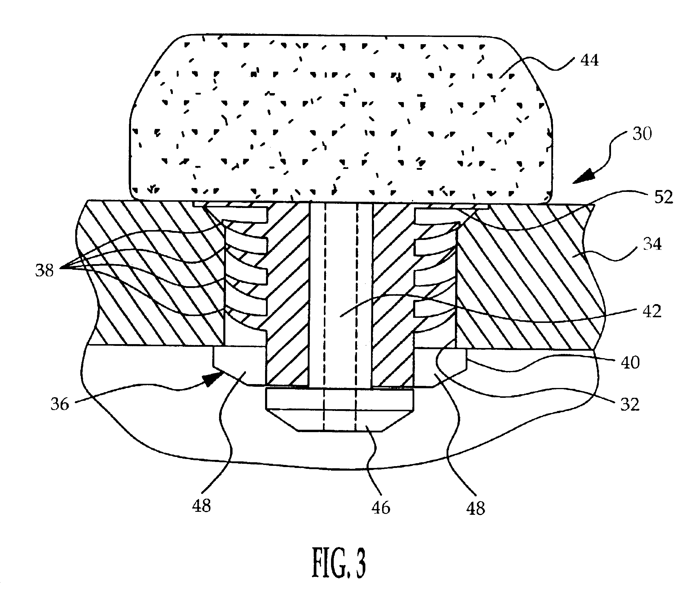
Referring to FIG. 3, the reference numeral 30 generally designates the pressure sensor assembly of the present invention as installed in an circular opening 32 formed in a pressure vessel wall 34. As mentioned above, the pressure vessel wall 34 may be the intake manifold of an internal combustion engine or a motor vehicle fuel tank, for example. In either case, the gaseous medium constrained by the wall 34 is subject to sudden positive pressure surges that tend to expel the sensor assembly 30 from the opening 32.

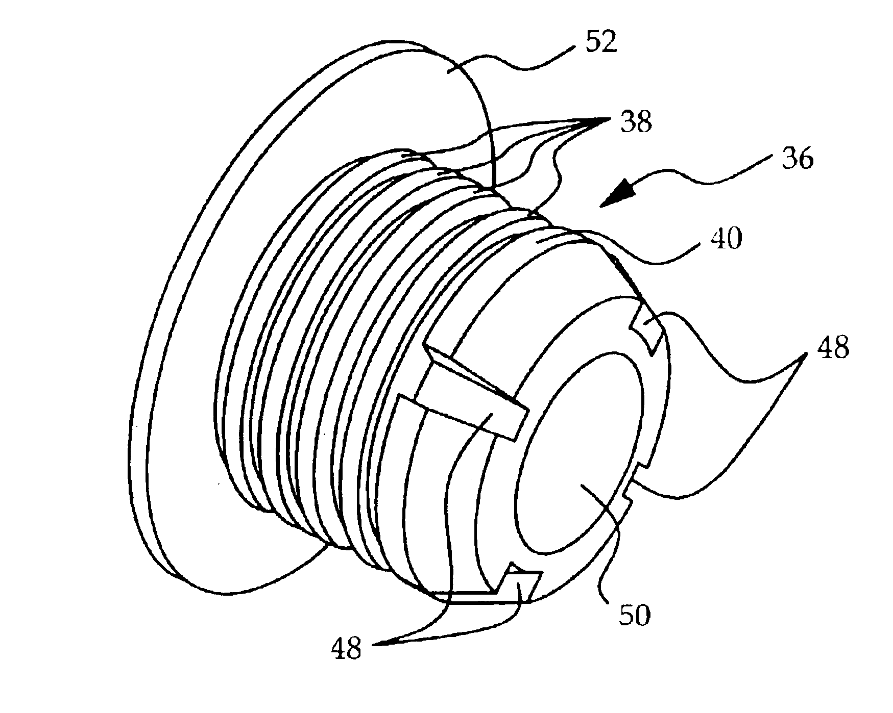
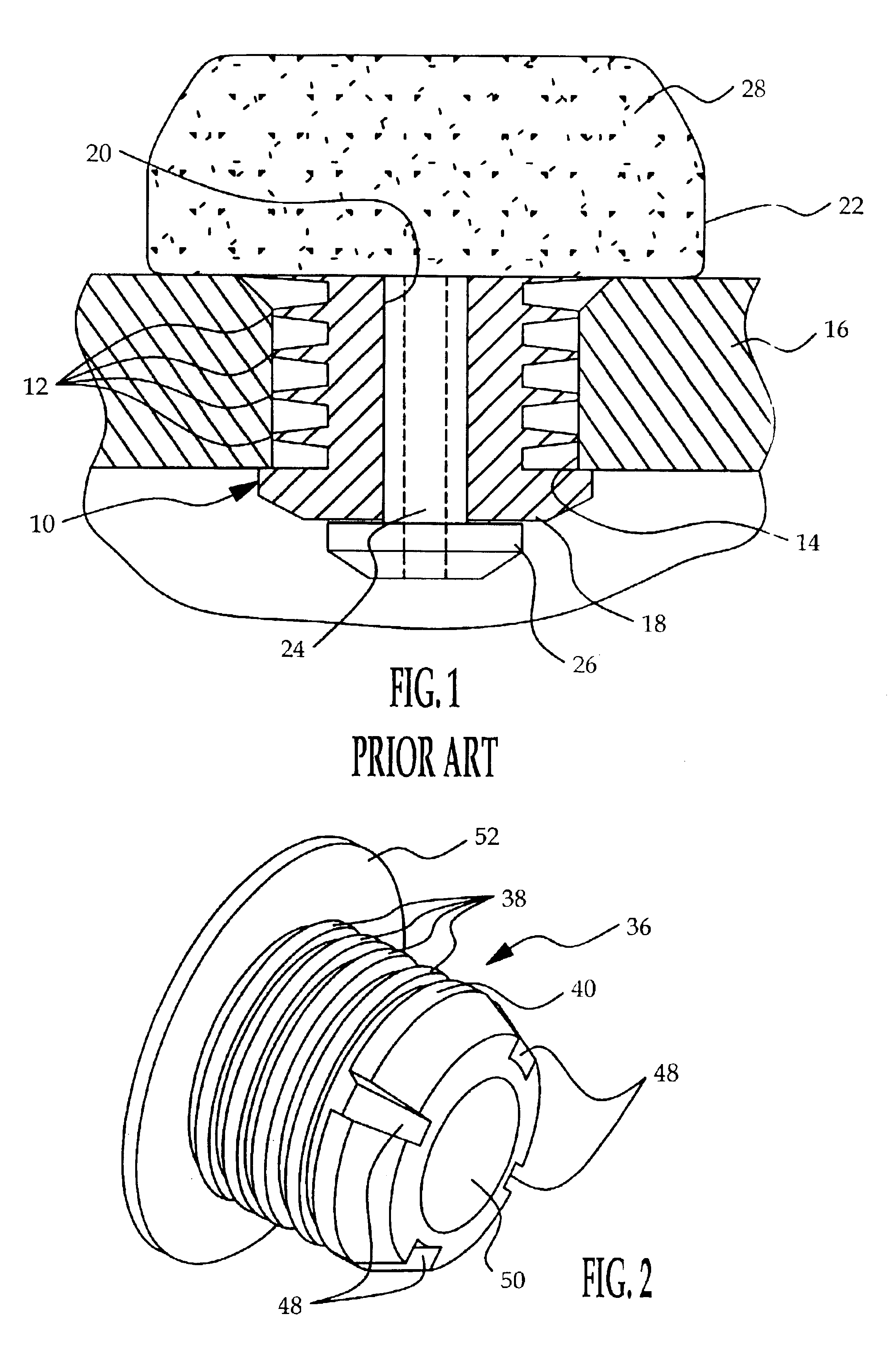
As with the prior art pressure sensor assembly depicted in FIG. 1, the pressure sensor assembly 30 depicted in FIG. 3 includes a resilient, flexible seal 36 that serves the dual purpose of sealing the constrained medium from the ambient pressure and retaining the assembly 30 within the pressure vessel wall 34 during positive pressure surges of the constrained medium. In particular, the fins 38 of seal 36 provide a seal between the constrained medium and the ambient pressure,...


PUM

PropertyMeasurementUnit
angleaaaaaaaaaa
diameteraaaaaaaaaa
shapeaaaaaaaaaa

Abstract

An improved self-retaining pressure sensor assembly includes a pressure sensor having a housing, a depending ported stem terminated in an enlarged foot, and a flanged resilient seal disposed about the stem between the pressure sensor housing and foot, with the seal flange having one or more notches about its circumferential periphery to ease insertion and extraction of the assembly with respect to a circular opening formed in a pressure vessel. The notches reduce the effective area of the flange, proportionately decreasing the force (insertion force) needed to insert the assembly at the time of installation and the force (extraction force) needed to subsequently remove the assembly for repair or replacement. The number and size of the notches can be adjusted to provide acceptable insertion and extraction forces, without lubricant, while not significantly compromising the self-retention capability of the assembly.

Description

TECHNICAL FIELDThis invention relates to a pressure sensor assembly including a resilient seal for sealing a pressure vessel opening and retaining the pressure sensor in the opening, and more particularly to a seal that provides reduced and controlled insertion and extraction forces.BACKGROUND OF THE INVENTIONMotor vehicle engine controls sometimes require measurement of gas pressures subject to positive pressure fluctuations that tend to expel or blow out the pressure sensor. For example, the gas pressure in the intake manifold of an internal combustion engine experiences a sudden positive surge during an engine backfire. A similar condition can occur with a fuel tank vapor pressure sensor in the event of a crash. Although the usual solution in such applications is to use screw fasteners or the like to secure the pressure sensor to the wall of the pressure vessel, it has been found that the sensor can be adequately secured with significant reductions in material and assembly expens...

Claims


Application Information

Patent Timeline
Patent Type & Authority Patents(United States)
IPC IPC(8): G01L19/00
CPCG01L19/0007
Inventor KUZNIA, PHILIP D.PITZER, PAUL J.JOHNSON, CLYDE H.
Owner DELPHI TECH IP LTD
Why Eureka
Try Eureka