Adjustment device for a compound miter saw

a technology of adjustment device and miter saw, which is applied in the direction of metal sawing device, metal sawing apparatus, manufacturing tools, etc., can solve the problems of inconvenient operation of modified adjustment device, easy slippage from the desired position, and increased difficulty in rotating the turning disk (63)

Inactive Publication Date: 2004-08-24
P & F BROTHER INDAL
View PDF8 Cites 37 Cited by
  • Summary
  • Abstract
  • Description
  • Claims
  • Application Information

AI Technical Summary

Problems solved by technology

However, the conventional adjustment device for a compound miter saw that uses the restitution force of the spring (61) to push the ball (62) into a detent (64) may easily slip from the desired position.
Although the adjustment device has been modified to increase the restitution force of the spring (61) to improve the connection between the ball (62) and the detents (64), the increased restitution force of the spring (61) will cause rotating the turning disk (63) more difficult.
The modified adjustment device is inconvenient to operate.

Method used


Image

  • Adjustment device for a compound miter saw
  • Adjustment device for a compound miter saw
  • Adjustment device for a compound miter saw

Examples


Embodiment Construction

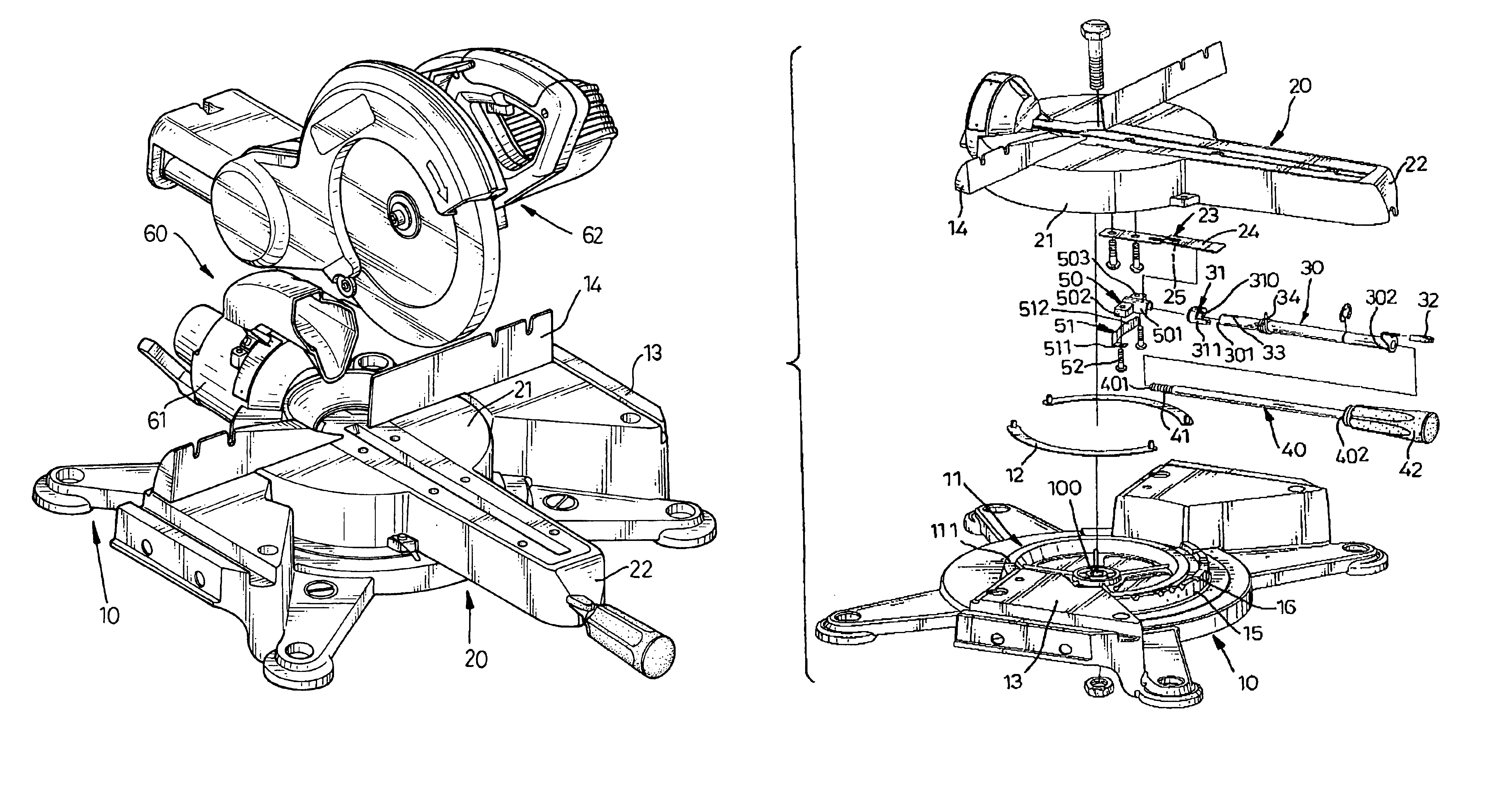
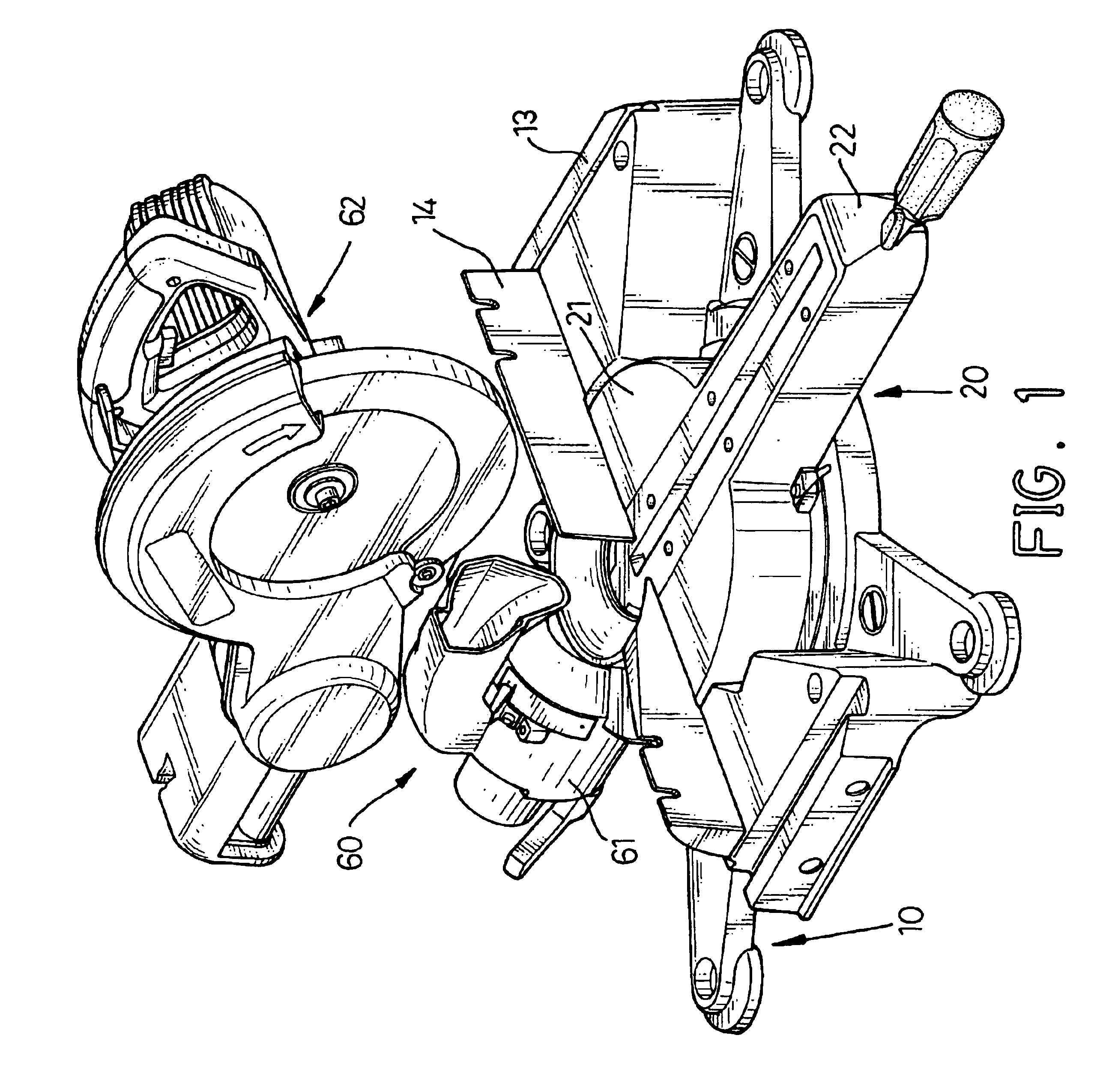
With reference to FIG. 1, a compound miter saw comprises a base (10), a turntable (20), a saw assembly (60), two supports (13) and a fence (14). The turntable (20) is rotatably mounted on the base (10). The saw assembly (60) is attached to the turntable (20) and comprises a connecting assembly (61) and a power saw assembly (62). The connecting assembly (61) is attached to the turntable (20) and the power saw assembly (62) is pivotally attached to the connecting assembly (61). The power saw assembly (62) can be pivoted toward the turntable (20) to cut a piece (not shown). The supports (13) have a top surface (not numbered) for supporting a piece (not shown) to be cut and are attached respectively to opposite sides of the base (10). The fence (14) is two pieces (not numbered) that have aligned front flat surfaces (not numbered) and are attached respectively to the top surface of each support (13). A piece to be cut abuts the front flat surfaces and is held in position by the fence (14...


PUM

PropertyMeasurementUnit
resilientaaaaaaaaaa
restitution forceaaaaaaaaaa
angleaaaaaaaaaa

Abstract

An adjustment device for a compound miter saw includes a base having a top and a miter lip with detents, a turntable having a bottom and a miter assembly. The turntable is rotatably mounted on the top of the base, and the miter assembly is attached to the bottom of the turntable. The miter assembly includes a resilient biasing member having an engaging stop corresponding to the detents, a releasing rod rotatably mounted in the turntable, and an eccentric rotator having an eccentric portion and attached to the releasing rod corresponding to the resilient biasing member. The releasing rod rotates the eccentric rotator so the eccentric portion will push the engaging stop upward to disengage it from the detents to allow the turntable to be adjusted.

Description

1. Field of the InventionThe present invention relates to an adjustment device for a compound miter saw, and more particularly to an adjustment device to efficiently position the compound miter saw to cut an angle in a workpiece.2. Description of Related ArtCompound miter saws are used to cut a piece of metal, wood or other material at a precise angle. Many applications require that a piece have an angled end, called a chamfer. Compound miter saws today have an adjustment device to adjust the saws to cut a piece at a specific angle.With reference to FIG. 7, a conventional adjustment device (not numbered) for a compound miter saw (not shown) comprises a base (60), and a turning disk (63). The base (60) has a spring (61) and ball (62) combination, a top (not numbered), a center (not numbered), a central opening (not numbered) and a spring-ball hole (not numbered). The central opening is defined through the top at the center of the base (60). The spring-ball hole is defined in the top ...

Claims


Application Information

Patent Timeline
Patent Type & Authority Patents(United States)
IPC IPC(8): B23D45/04B23D47/02B23D47/00B23D45/00
CPCB23D45/048B23D47/025B27B5/29Y10T83/768Y10T83/7697Y10T83/7705Y10T83/7788Y10T83/8773
Inventor KAO, MEI-LAN
Owner P & F BROTHER INDAL
Why Eureka
Try Eureka