Damped micromechanical device

a micromechanical device and damping technology, applied in the direction of generator/motor, acceleration measurement using interia forces, instruments, etc., can solve the problems of not providing damping in air, being susceptible to external vibration or shock, and limiting attempts to control damping of such devices, so as to limit mechanical motion

Inactive Publication Date: 2004-09-07
COHERENT INC
View PDF8 Cites 41 Cited by
  • Summary
  • Abstract
  • Description
  • Claims
  • Application Information

AI Technical Summary

Benefits of technology

For micromechanical devices fabricated in materials such as silicon, silicon dioxide, silicon nitride, or metals such as aluminum or nickel, the inherent damping of the structural material itself is extremely low. For example, electrostatic microactuators manufactured using deep reactive ion etched (DRIE) techniques often have comb gaps on the order of ten microns and thus do not provide damping in air that is sufficient for using such microactuators as positionable actuators. As a result, such devices typically have measurements of the mechanical quality factor Q in a vacuum that are typically greater than 5,000 and are potentially susceptible to external vibration or shock, especially from disturbances closely matching the frequency of one of the mechanical resonant modes of the device. It is thus important to control the damping of micromechanical devices.

Problems solved by technology

For example, electrostatic microactuators manufactured using deep reactive ion etched (DRIE) techniques often have comb gaps on the order of ten microns and thus do not provide damping in air that is sufficient for using such microactuators as positionable actuators.
As a result, such devices typically have measurements of the mechanical quality factor Q in a vacuum that are typically greater than 5,000 and are potentially susceptible to external vibration or shock, especially from disturbances closely matching the frequency of one of the mechanical resonant modes of the device.
Although viscous damping of micromechanical devices occurs from the dissipation of energy resulting from the motion of fluid, such as air or liquid, in which the device resides, attempts to control the damping of such devices have been limited.

Method used


Image

  • Damped micromechanical device
  • Damped micromechanical device
  • Damped micromechanical device

Examples


Embodiment Construction

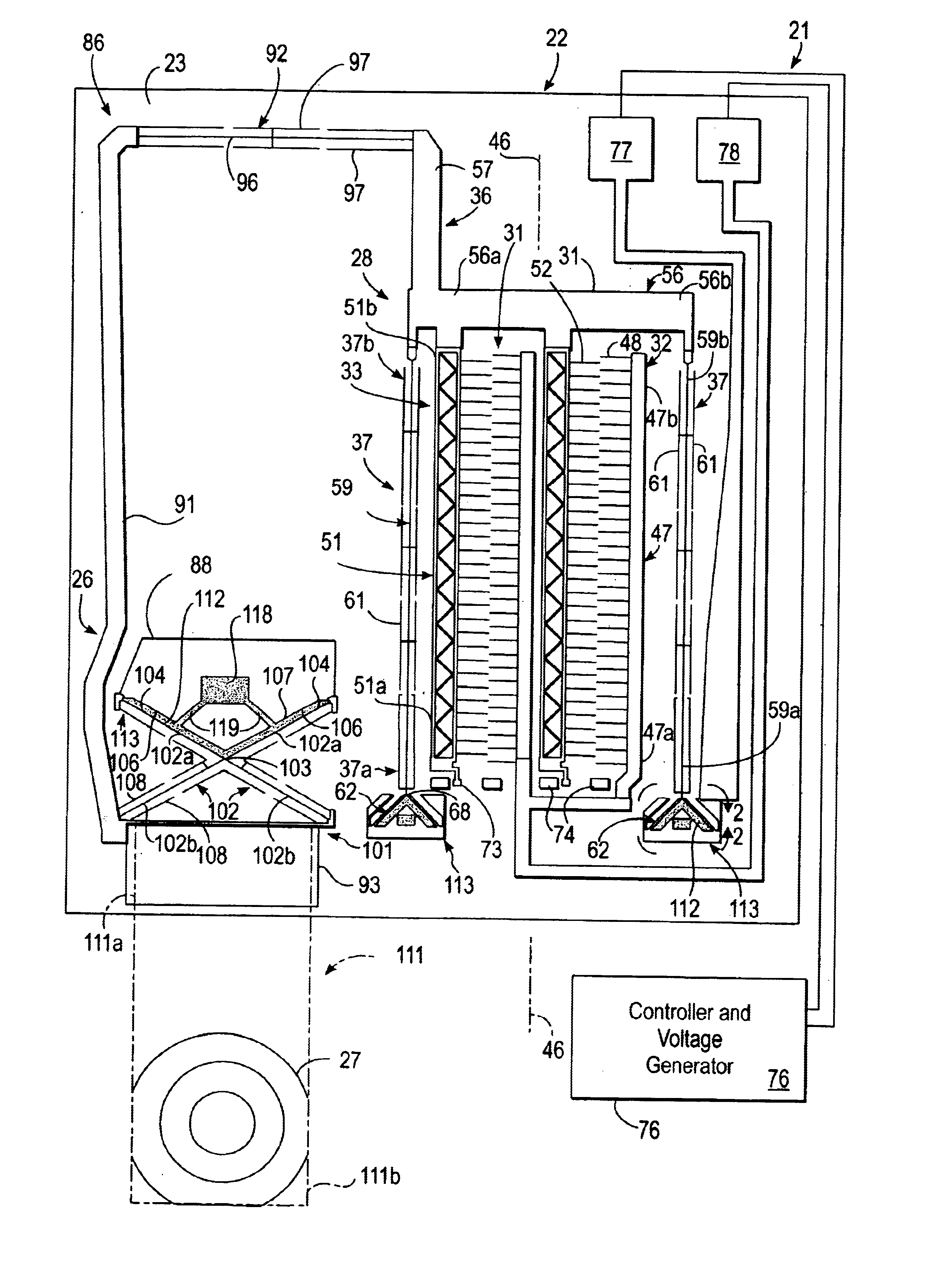
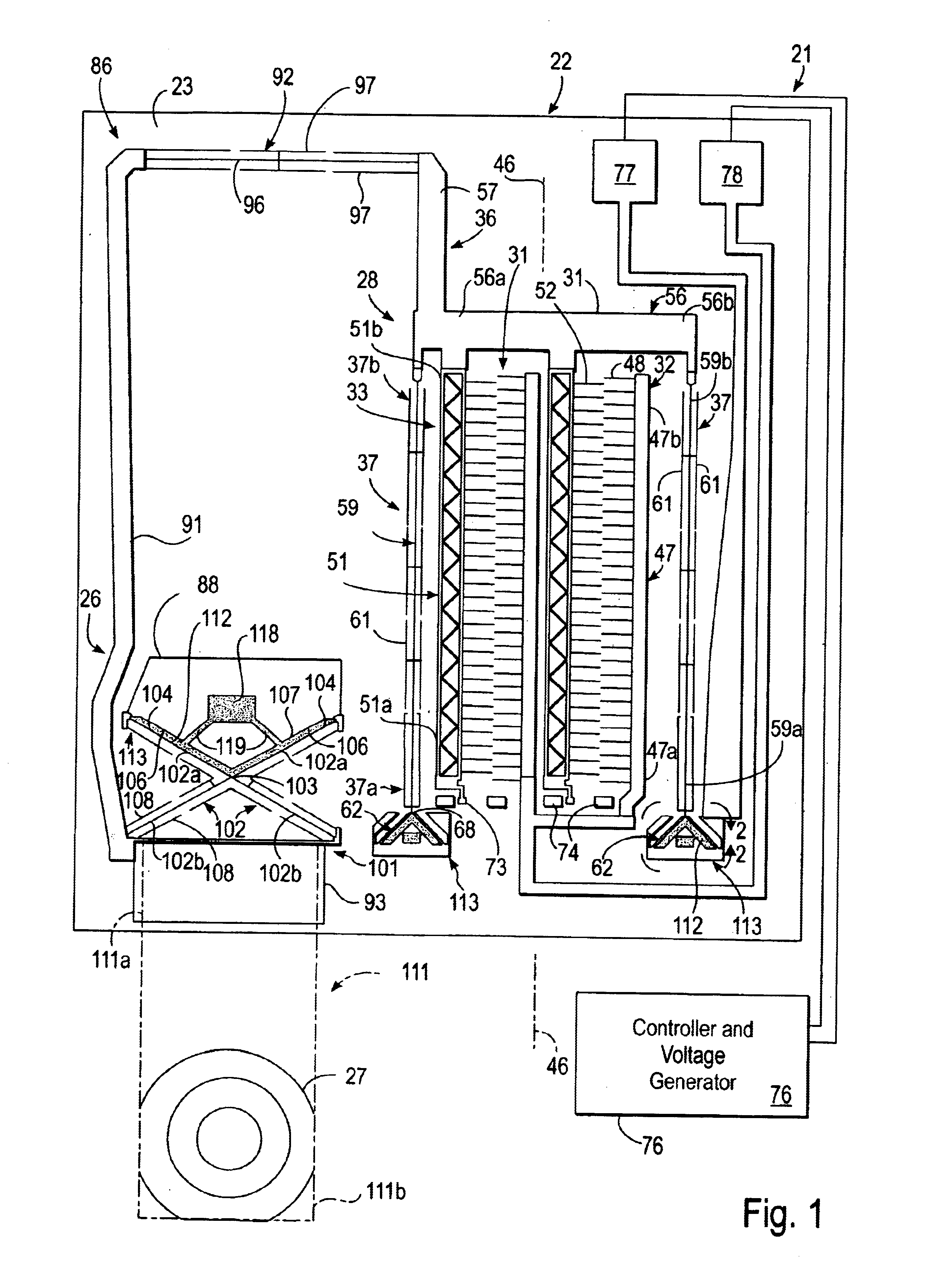
The micromechanical device of the present invention can be in the form of a lens adjuster 21, shown in FIG. 1, suitable for use in a tunable laser of the type disclosed in U.S. patent application Ser. No. 09 / 728,212 filed Nov. 29, 2000 (Our file number A-70056), the entire content of which is incorporated herein by this reference. In general, lens adjuster 21 includes a microactuator 22 formed on a substrate 23 and coupled to a lever assembly 26. A collimating lens 27 is carried by the lever assembly 26.

Microactuator 22 can be of any suitable type, such as an electromagnetic microactuator or any other electrically-driven microactuator, but is preferably an electrostatic microactuator. The microactuator 22 has similarities to the microactuators disclosed in U.S. Pat. No. 6,384,510 and U.S. Pat. No. 6,469,415, the entire content of each of which is incorporated herein by this reference. In this regard, microactuator 22 is formed on planar substrate 23 and has a movable structure 28 th...


PUM


Abstract

A damped micromechanical device comprising a substrate, a movable structure overlying the substrate and a flexural member having a first end portion coupled to the substrate and a second end portion coupled to the movable structure. The movable structure is movable at a resonant frequency between first and second positions relative to the substrate. A damping material is adhered to at least a portion of the flexural member for damping the movement of the movable structure at the resonant frequency. A method for making the micromechanical device is provided.

Description

SCOPE OF THE INVENTIONThe present invention relates generally to micromechanical devices and more particularly to damped micromechanical devices.Micromechanical devices have heretofore been provided, and include sensors such as accelerometers, angular rate sensors and gyroscopes and optical devices such as optical switches, scanners, interferometers and tunable filters. Each of such devices includes a moving structure supported by flexural elements and is thus a spring mass system having one or more mechanical resonant modes. These modal frequencies are typically estimated through the use of finite element analysis. A mechanical quality factor or Q, which is a measure of the damping associated with the motion of the part, can be associated with each of these resonant modes.For micromechanical devices fabricated in materials such as silicon, silicon dioxide, silicon nitride, or metals such as aluminum or nickel, the inherent damping of the structural material itself is extremely low....

Claims


Application Information

Patent Timeline
Patent Type & Authority Patents(United States)
IPC IPC(8): B81B7/00B81B3/00H02N1/00
CPCB81B3/0051H02N1/008B81B2203/0136
Inventor GRADE, JOHN D.JERMAN, JOHN H.YASUMURA, KEVIN Y.DRAKE, JOSEPH D.
Owner COHERENT INC
Why Eureka
Try Eureka