Homogenization device and method of using same

a technology of homogenizing device and homogenizing method, which is applied in the direction of non-electric variable control, process and machine control, instruments, etc., to achieve the effect of maintaining homogenizing quality and efficiency

Inactive Publication Date: 2004-10-12
ARISDYNE STSTEMS INC
View PDF14 Cites 62 Cited by
  • Summary
  • Abstract
  • Description
  • Claims
  • Application Information

AI Technical Summary

Benefits of technology

A yet still further aspect of the present invention is to provide a homogenization device having an adjustable orifice for providing a controlled orifice length in an inexpensive and readily adjustable manner.
A yet still further aspect of the present invention is to provide a homogenization device having an adjustable orifice that permits an operator to adjust the length of the orifice to change the flow rate through the device, while maintaining the homogenizing quality and efficiency.
Another embodiment according to the present invention provides a homogenizer device comprising a housing having an inlet opening for introducing fluid into the device, an outlet opening for exiting fluid from the device, and a flow-through channel in fluid communication with the inlet opening. The flow-through channel has a longitudinal axis and is defined by at least one wall where the at least one wall has a first orifice disposed therein to provide fluid communication between the flow-through channel and the outlet opening. Preferably, the first orifice has an upstream end and a downstream end defining a length therebetween that is parallel to the longitudinal axis of the flow-through channel. A baffle element is also disposed within the flow-through channel between the upstream end and downstream end thereby defining a second orifice between the perimeter of the baffle element and the at least one wall. The baffle element also defines an effective length of the first orifice defined as the axial distance between the upstream end of the first orifice and the baffle element. The baffle element is also movable within the flow-through channel between the upstream end and the downstream end of the first orifice to change the effective length of the first orifice thereby adjusting the flow rate of fluid through the orifice while maintaining the flow rate of fluid through the second orifice.

Problems solved by technology

By subsequently exposing the turbulent shear layer to a sufficient high downstream pressure, the bubbles collapse violently and cause extremely high pressure shocks which cause intermittent intermixing of the multicomponent stream.

Method used


Image

  • Homogenization device and method of using same
  • Homogenization device and method of using same
  • Homogenization device and method of using same

Examples


Embodiment Construction

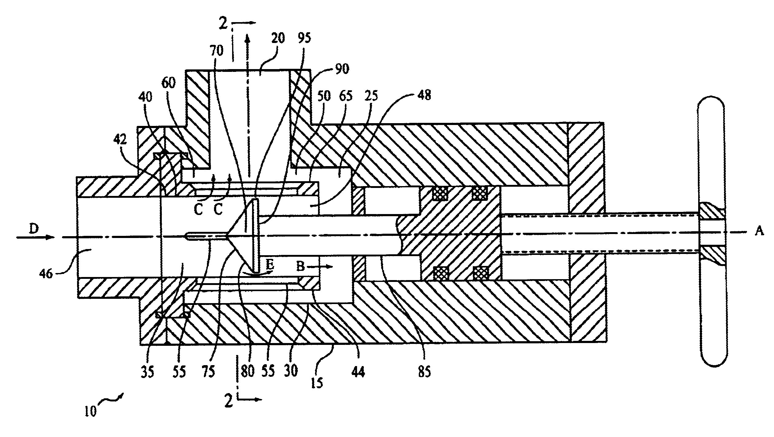
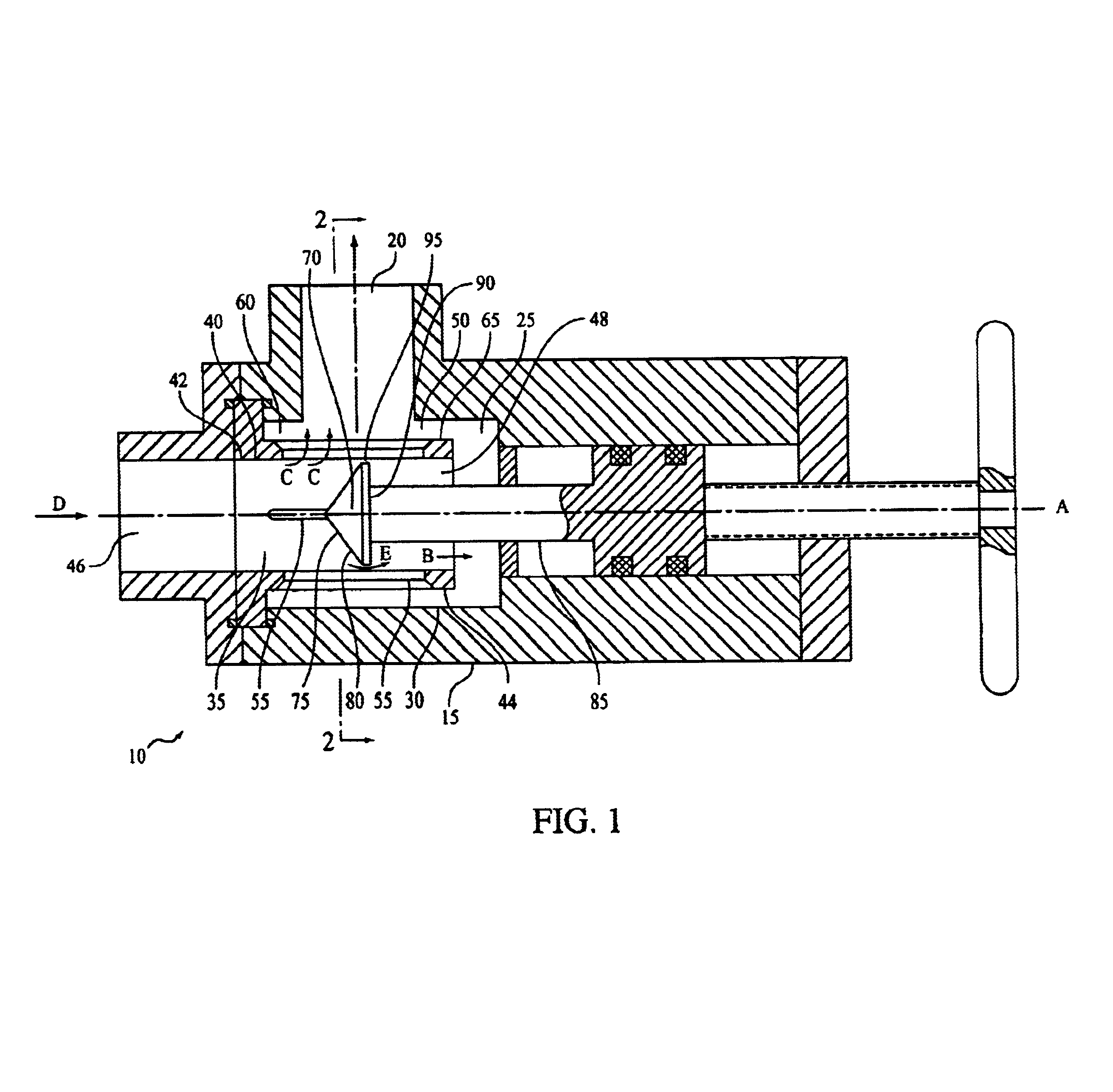
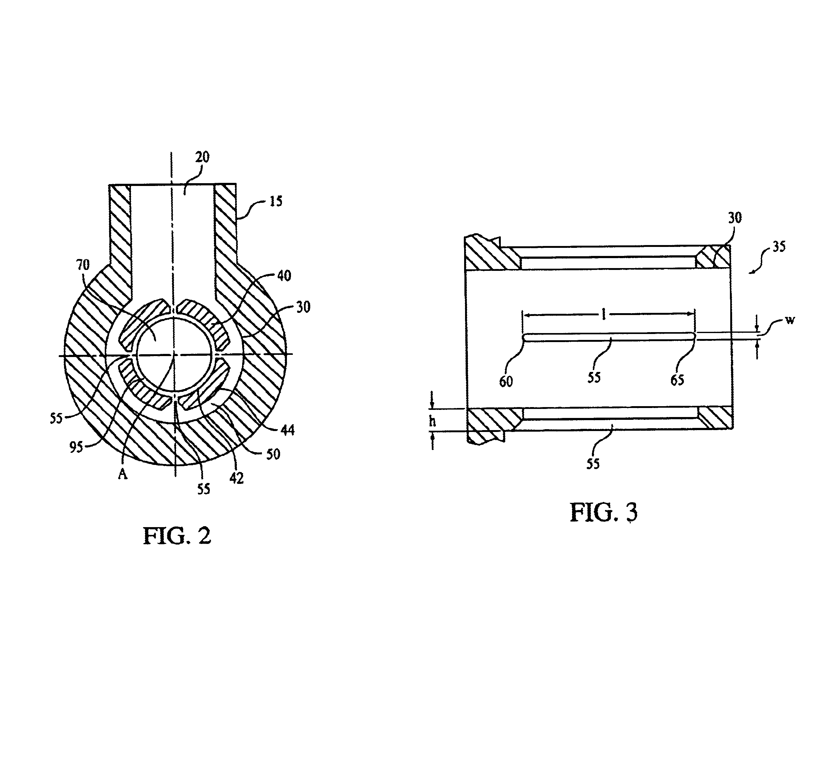
In accordance with this invention, and as shown in FIG. 1, a homogenization device 10 according to the present invention comprises a housing 15 having an outlet opening 20 for exiting fluid and dispersants from device 10 and an internal cylindrical chamber 25 (hereinafter referred to as "internal chamber 25") defined by an inner cylindrical surface 30. Internal cylindrical chamber 25 has a longitudinal axis A and is in fluid communication with outlet opening 20. Although it is preferred that the cross-section of internal chamber 25 is circular, the cross-section of internal chamber 25 may take the form of any geometric shape such as square, rectangular, or hexagonal and still be within the scope of the present invention.

Device 10 further comprises a flow-through channel 35 defined by a cylindrical wall 40 having an inner surface 42, an outer surface 44, an inlet opening 46 for introducing fluid into device 10, and an outlet opening 48. Although it is preferred that the cross-section...


PUM

PropertyMeasurementUnit
lengthaaaaaaaaaa
flow rateaaaaaaaaaa
widthaaaaaaaaaa

Abstract

A homogenization device comprising a flow-through channel having at least two local constrictions of flow wherein the size of a first local constrictions is adjustable thereby permitting variable flow rate through one portion of the device and the size of a second local constriction is fixed thereby permitting constant flow rate through another portion of the device.

Description

The present invention relates in general to a homogenization device and more particularly to an homogenization device having an adjustable orifice and even more particularly to a homogenization device having an adjustable orifice for homogenization of a multi-component stream, having a liquid component and a substantially insoluble component that may be either a liquid or a finely divided solid.In accordance with U.S. Pat. No. 4,127,332, there is disclosed a homogenization apparatus which provides an emulsion or colloidal suspension having an extremely long separation half-life by the use of cavitating flow. The prior art homogenization apparatus is constructed of a generally cylindrical conduit including an orifice plate assembly extending transversely thereacross and having an orifice opening provided therein. The orifice opening is described as embodying various designs such as circular blunt or sharp edged, square sharp edged and, a pair of substantially semi-circular annular se...

Claims


Application Information

Patent Timeline
Patent Type & Authority Patents(United States)
IPC IPC(8): B01F5/08B01F5/06B01F3/08B01F3/12B01F25/46
CPCB01F5/0662B01F5/08B01F5/0681B01F3/0807B01F3/12B01F23/41B01F23/50B01F25/441B01F25/4423B01F25/46
Inventor KOZYUK, OLEG V.
Owner ARISDYNE STSTEMS INC
Why Eureka
Try Eureka