Crimp for a jack

a technology of crimping and jacks, applied in the direction of unstripped conductor connection apparatus, coupling device connection, manufacturing tools, etc., can solve the problems of significant number of limitations, inefficient and time-consuming, and user disorientation of the crimping tool

Inactive Publication Date: 2004-10-26
FOCUS STRATEGIES CAPITAL ADVISORS LLC +1
View PDF16 Cites 33 Cited by
  • Summary
  • Abstract
  • Description
  • Claims
  • Application Information

AI Technical Summary

Problems solved by technology

There are various drawbacks to using a single wire punch tool.
Such punch tools can only terminate one wire at a time and are thus inefficient and time-consuming.
There is also a possibility that the punched tool will be disoriented by the user relative to the wire and accidentally cut the wire on the inward side of the jack.
Although this design is workable, it has a significant number of limitations.

Method used


Image

  • Crimp for a jack
  • Crimp for a jack
  • Crimp for a jack

Examples


Embodiment Construction

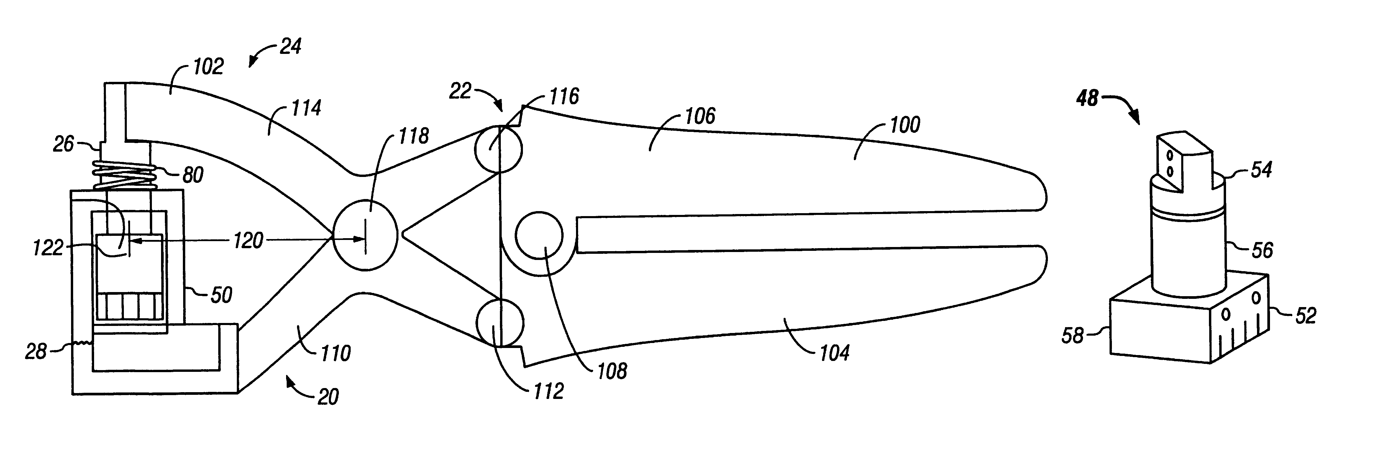
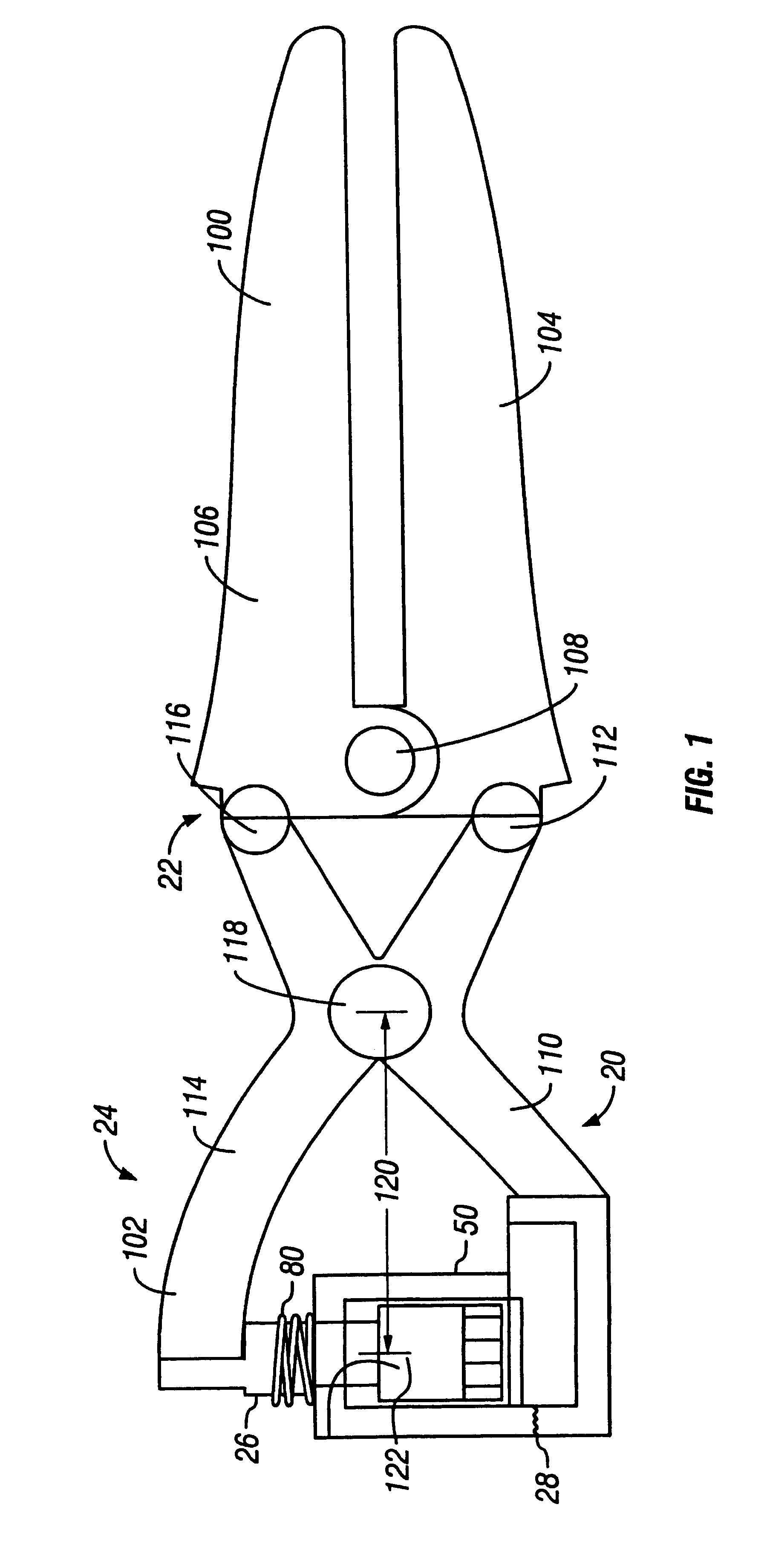
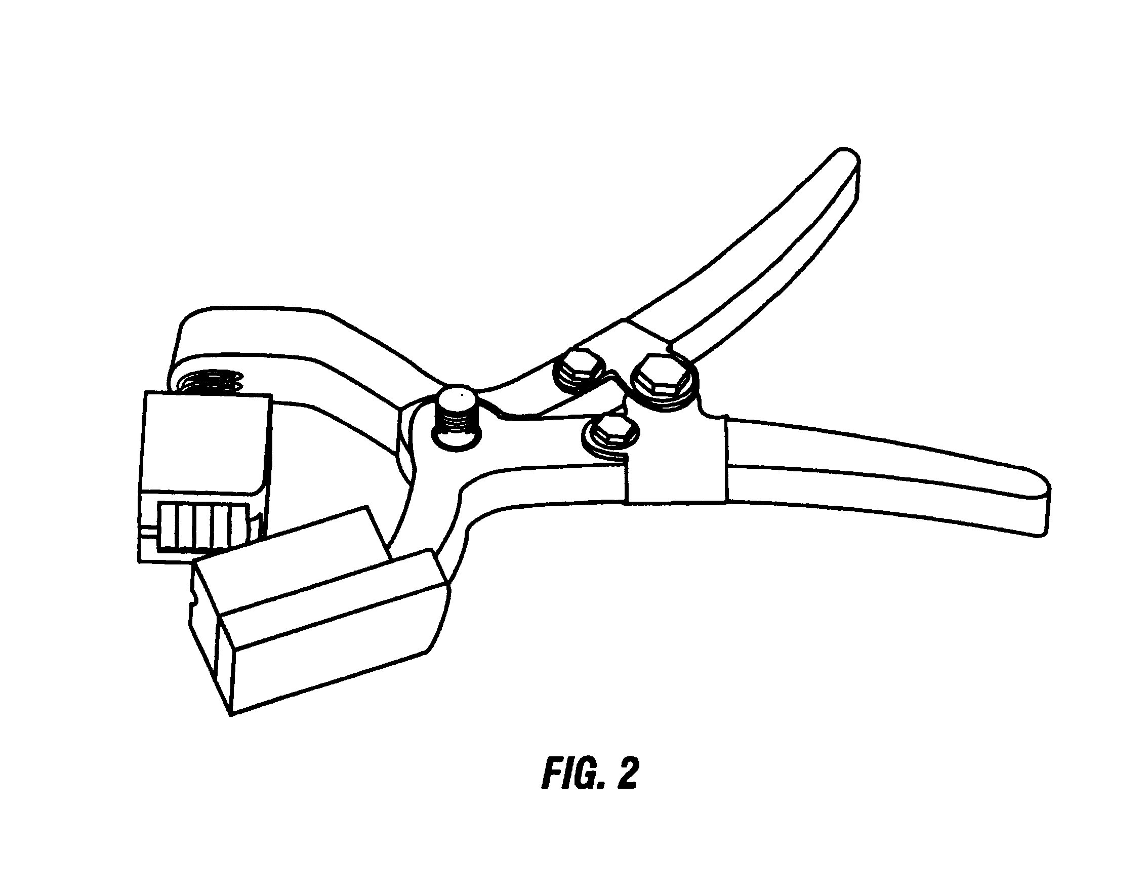
Referring now to FIGS. 1 and 2, apparatus 20 comprises a handle lever portion 22 and a crimp portion 24. The crimp portion 24 comprises a press 26 and a base housing 28. As shown in FIGS. 4, 5, 13, 16, 19, and 22, the base housing 28 comprises a placement location 30 that has a recessed surface 32 that is adapted to engage the outer surface of a jack. Located in the forward region of the base housing 28, is a recessed region 34 adapted to allow cable to pass therethrough. The base housing 28 further comprises lateral regions 36 that have a frictionally engaging surface portions 38 thereon that are adapted to clamp to wire ends which will be discussed further herein later in this text. The base housing 28 further has a base surface 40 (FIGS. 5a and 5c) that is adapted to support a jack housing therein during the clamping process.

As shown in FIGS. 3, 6, 7, 11, 12, 14, 15, 17, 18, 20, and 21, the aforementioned press 26 comprises a plunger 48 and a housing 50. As shown in FIG. 3, the p...


PUM

PropertyMeasurementUnit
timeaaaaaaaaaa
longitudinal distanceaaaaaaaaaa

Abstract

A crimping tool has a handle lever portion and a crimp portion with a press and a base housing. The base housing has a placement location with a recessed surface for engaging a jack and a recessed region for a cable. The base housing also has lateral regions that have frictionally engaging surface portions for clamping to wire ends. The press has a plunger and a housing with terminating blades for shearing excess wire from the cable when the tool engages a twisted pair cable to a jack. The blades cut the wires and the excess wire is discarded. The press and the base housing then disengage and the jack is removed from the tool with the cable in communication with the electrical contacts of the jack.

Description

1. Field of the InventionThe present invention relates generally to the crimping process network jacks, and more particularly to an improved crimping tool for terminating telecommunications cable conductors in an appropriate receptacle.2. Description of the Prior ArtIn installing computer networks, such as Category 5 cable with RJ45 jacks, a jack is installed at the end of the cable. To install a jack, four sets of twisted wire are unwound and placed on specific receiving portions of the jack. These receiving portions comprise sharp scissors-like means which cut the insulation of each wire and allows electrical communication between the jack and the wire.In the prior art, each wire in a multi-wire cable is typically individually punched into a receiving means with a single wire punch tool. When a wire is punched, the outward portion of the wire is cut off by a sharp portion of the punch tool. There are various drawbacks to using a single wire punch tool. Such punch tools can only te...

Claims


Application Information

Patent Timeline
Patent Type & Authority Patents(United States)
IPC IPC(8): B25B27/14H01R43/01
CPCB25B27/146H01R43/015H01R24/62Y10T29/53217Y10T29/5193Y10T29/53213Y10T29/53257Y10T29/5151Y10T29/53226Y10T29/53235Y10T29/53222
Inventor GRIFFIN, MICHELLEROHRBACH, STEVE
Owner FOCUS STRATEGIES CAPITAL ADVISORS LLC
Why Eureka
Try Eureka