Filter medium for turbine and methods of using and producing the same

a filter medium and turbine technology, applied in the direction of filtration separation, colloidal chemistry, separation processes, etc., can solve the problems of self-dusting of the medium, increased pressure loss during operation, and increased pressure loss of conventional filter medium using porous ptfe membrane in a shorter tim

Inactive Publication Date: 2004-10-26
NITTO DENKO CORP
View PDF37 Cites 55 Cited by
  • Summary
  • Abstract
  • Description
  • Claims
  • Application Information

AI Technical Summary

Problems solved by technology

However, the presence of adherent fibrils in such a medium causes self-dusting of the medium when the medium is bent in processing.
Therefore, when this filter medium of the laminate type is used, an increase in pressure loss is caused during operation in a shorter time than in the case of using the glass fiber medium.
Thus, when used as a filter medium for a turbine, a conventional filter medium using the porous PTFE membrane is increased in pressure loss in a shorter time.
However, when the fiber diameter is too small, the air-permeable supporting member is decreased in strength, and thus the function of the air-permeable supporting member as the reinforcing member is sometimes impaired.
When a conductor is brought close to the filter medium with a surface potential increased due to the electric charging or the filter medium is touched with a bare hand of a human, in some cases, sparks are caused to form a through hole in the filter medium.
When the filter medium is too thick, in some cases, pressure loss is increased, and a pleating property is degraded.

Method used


Image

  • Filter medium for turbine and methods of using and producing the same
  • Filter medium for turbine and methods of using and producing the same
  • Filter medium for turbine and methods of using and producing the same

Examples


example 1

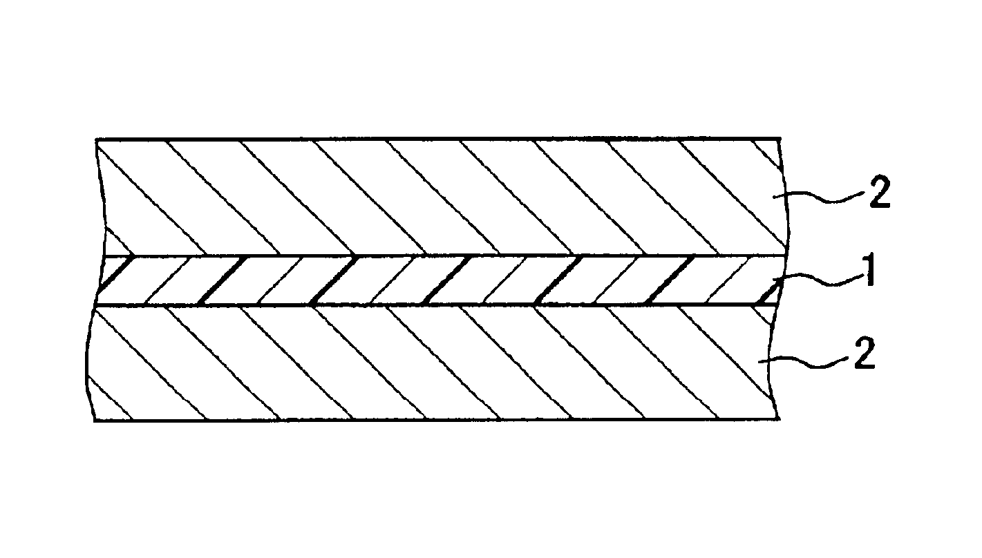
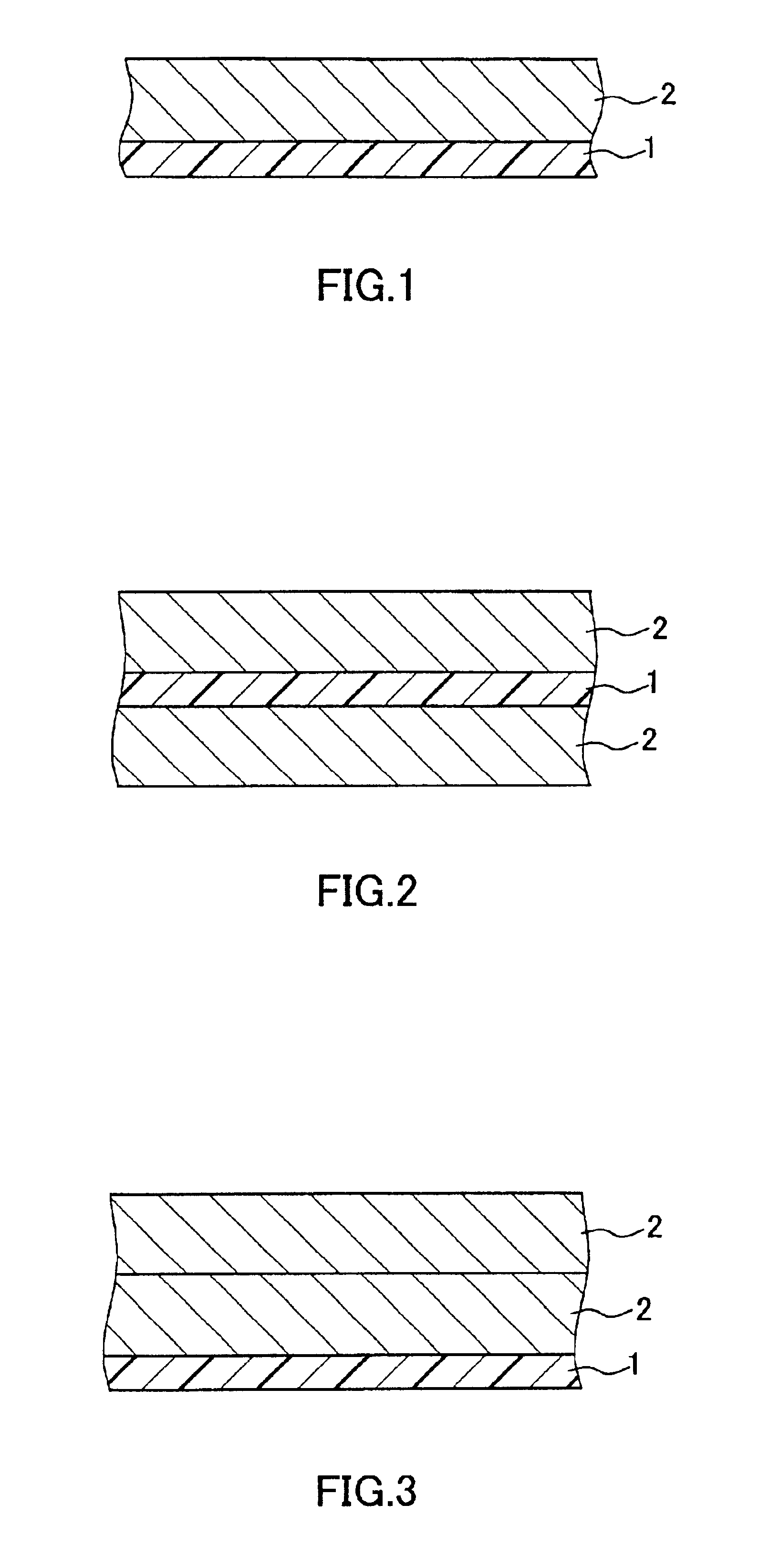
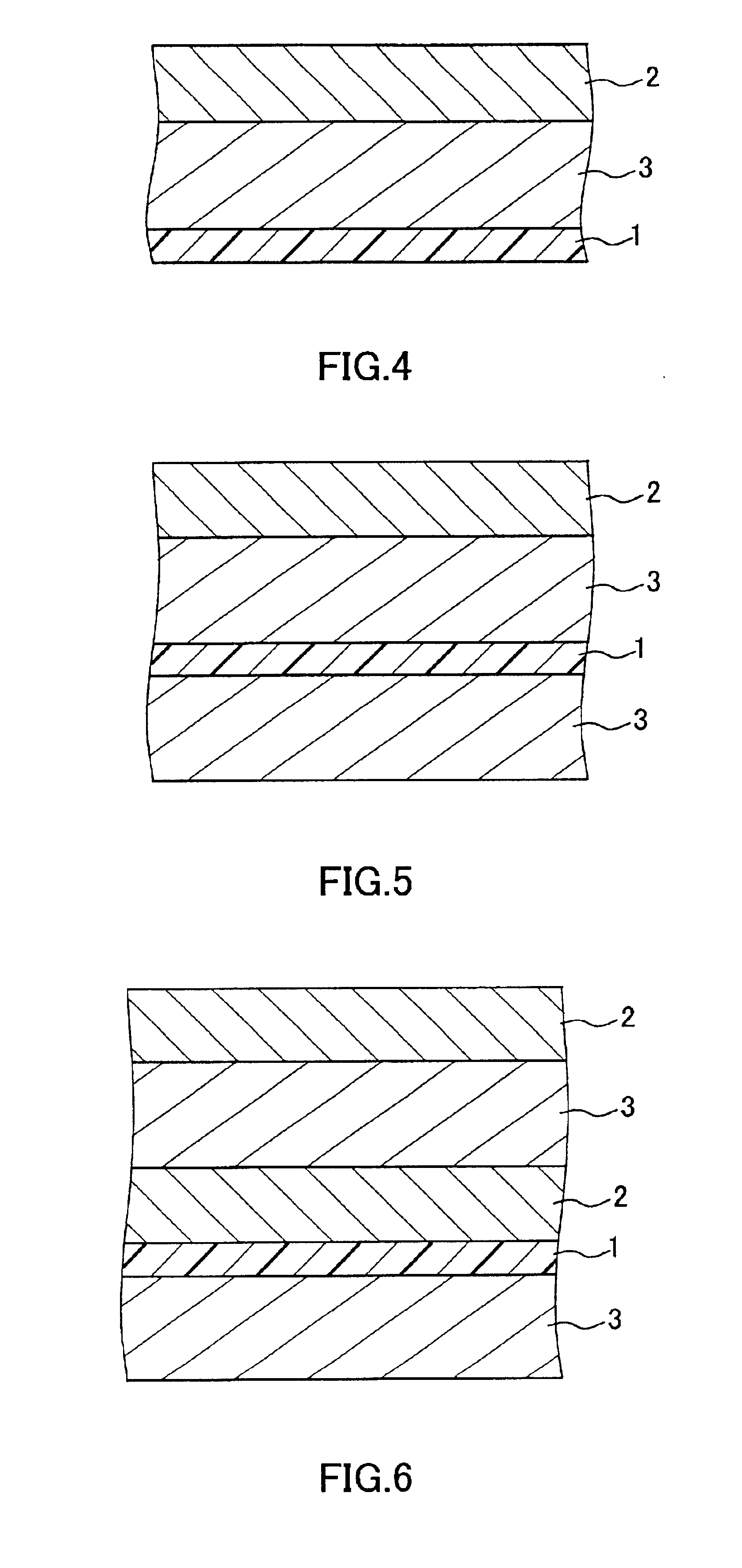
Preforming of a pastelike mixture formed by adding 30 parts by weight of a liquid lubricant (liquid paraffin) to 100 parts by weight of a fine PTFE powder is performed. Then, a preform thus obtained was formed into a shape of a round bar by the paste extrusion. A molding thus obtained was stretched under pressure to a thickness of 0.2 mm, and the liquid lubricant was removed by extraction using normal decane. Then, the molding was stretched in a longitudinal direction under a temperature of 300.degree. C. at a stretching ratio of 10 times and subsequently in a lateral direction under a temperature of 120.degree. C. at a stretching ratio of 30 times. The molding was subjected further to firing under a temperature of 400.degree. C. for 0.5 seconds. In this manner, a porous PTFE membrane (thickness: 10 .mu.m, porosity: 93%, average pore diameter: 1.0 .mu.m, average fiber diameter: 0.2 .mu.m, pressure loss: 176.5 Pa, collection efficiency: 99.999%) was obtained.

As the air-permeable supp...

example 2

A filter medium for a turbine having a thickness of 0.20 mm was obtained in the same manner as in the case of Example 1 except that as the air-permeable supporting member, a PP nonwoven fabric having a fiber diameter of about 2 to 5 .mu.m (average diameter: about 3.5 .mu.m) and a basis weight of 30 g / m.sup.2 was used.

example 3

A filter medium for a turbine having a thickness of 0.22 mm was obtained in the same manner as in the case of Example 1 except that as the air-permeable supporting member, a PP nonwoven fabric having a fiber diameter of about 7 to 12 .mu.m (average diameter: about 10 .mu.m) and a basis weight of 30 g / m.sup.2 was used.


PUM

PropertyMeasurementUnit
diameteraaaaaaaaaa
diameteraaaaaaaaaa
diameteraaaaaaaaaa

Abstract

The present invention is to provide a filter medium for a turbine in which contamination is less likely to be caused in the turbine, and an increase in pressure loss is suppressed. One form of this filter medium includes a porous polytetrafluoroethylene (PTFE) membrane and an air-permeable supporting member. The air-permeable supporting member has a fiber diameter of not more than 15 mum. This filter medium is used by disposing the air-permeable supporting member on an upstream side of the porous PTFE membrane with respect to air flow passing through the filter medium toward the turbine. Another form of the filter medium of the present invention includes a porous PTFE membrane, a first air-permeable supporting member, and a second air-permeable supporting member.

Description

1. Field of the InventionThe present invention relates generally to a filter medium for a turbine including a porous polytetrafluoroethylene (hereinafter, abbreviated as "PTFE") membrane. More specifically, this invention relates to a filter medium that is used at an intake side of a gas turbine or a steam turbine installed in a power plant or the like and suited for the collection of airborne particles in the air or a gas.This application claims priority under the Paris Convention of Japanese patent applications Nos. 2001-179026 and 2001-179027, which are hereby incorporated by reference.2. Related Background ArtConventionally, as a filter medium used at an intake side of a turbine, a medium formed by adding a binder to glass fibers and forming a resultant material into a sheet has been in common use. However, the presence of adherent fibrils in such a medium causes self-dusting of the medium when the medium is bent in processing. These fibrils of the glass fibers fall off a filter...

Claims


Application Information

Patent Timeline
Patent Type & Authority Patents(United States)
IPC IPC(8): B01D39/16
CPCB01D39/163B01D39/1692Y10S55/05
Inventor KAWANO, EIZOUMAEOKA, TAKUYA
Owner NITTO DENKO CORP
Why Eureka
Try Eureka