
Control apparatus for continuously variable transmission

a technology of control apparatus and transmission shaft, which is applied in mechanical apparatus, instruments, transportation and packaging, etc., can solve the problems of engine torque being insufficient and engine being burdened with possible over-revolution

Inactive Publication Date: 2004-11-23
HONDA MOTOR CO LTD
View PDF4 Cites 34 Cited by
  • Summary
  • Abstract
  • Description
  • Claims
  • Application Information

AI Technical Summary

Benefits of technology

Ensures proper engine torque and prevents over-revolution by maintaining dynamic transmission ratio adjustments, allowing drivers to feel and recognize mode changes, thus enhancing operational safety and efficiency.

Problems solved by technology

For this reason, if the driver performs the aforementioned switching and shifts the transmission to the High side in a situation where the vehicle is climbing up a slope and therefore requires a high engine torque, the engine torque can be insufficient.
Also, if the aforementioned switching is caused by an erroneous operation, the driver is often unaware that the continuously variable transmission has been switched to the manual mode because the transmission ratio of the continuously variable transmission is fixed at a constant transmission ratio.
Therefore, for example, if the driver keeps treading down the accelerator pedal for acceleration without being aware that the transmission has been shifted to the Low side upon switching, the engine would be burdened with possible over-revolution.

Method used


Image

  • Control apparatus for continuously variable transmission
  • Control apparatus for continuously variable transmission
  • Control apparatus for continuously variable transmission

Examples


Embodiment Construction

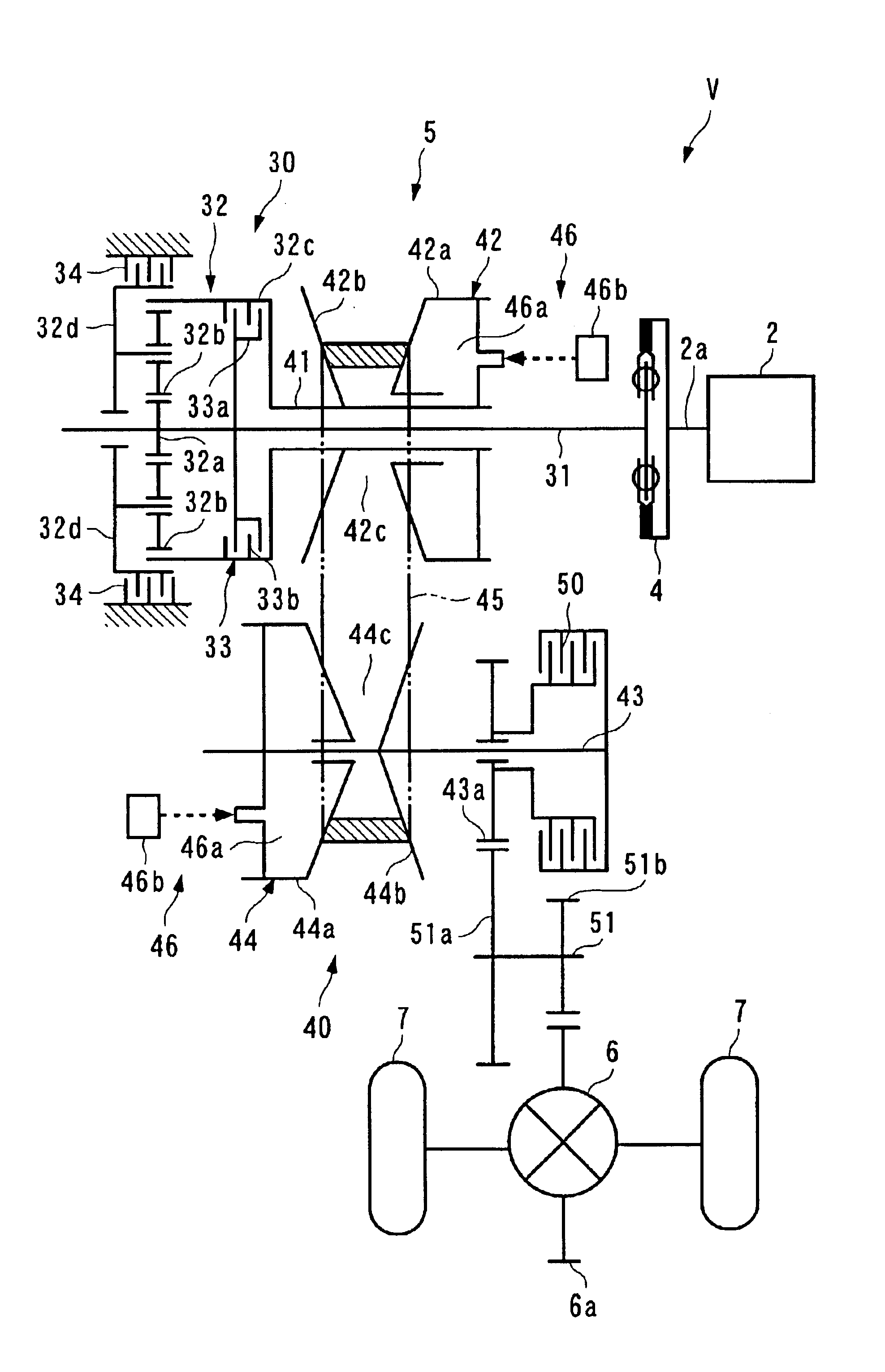
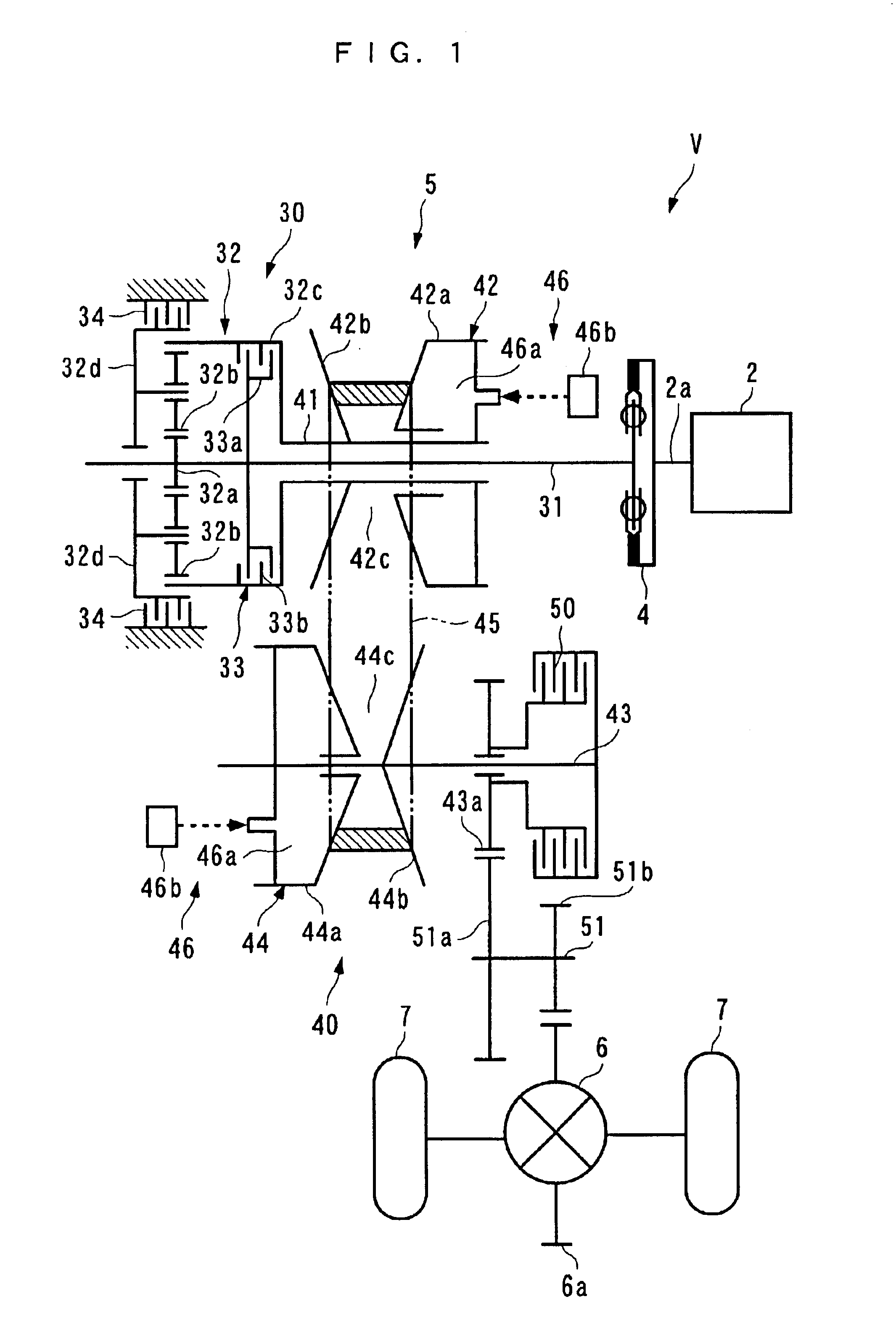
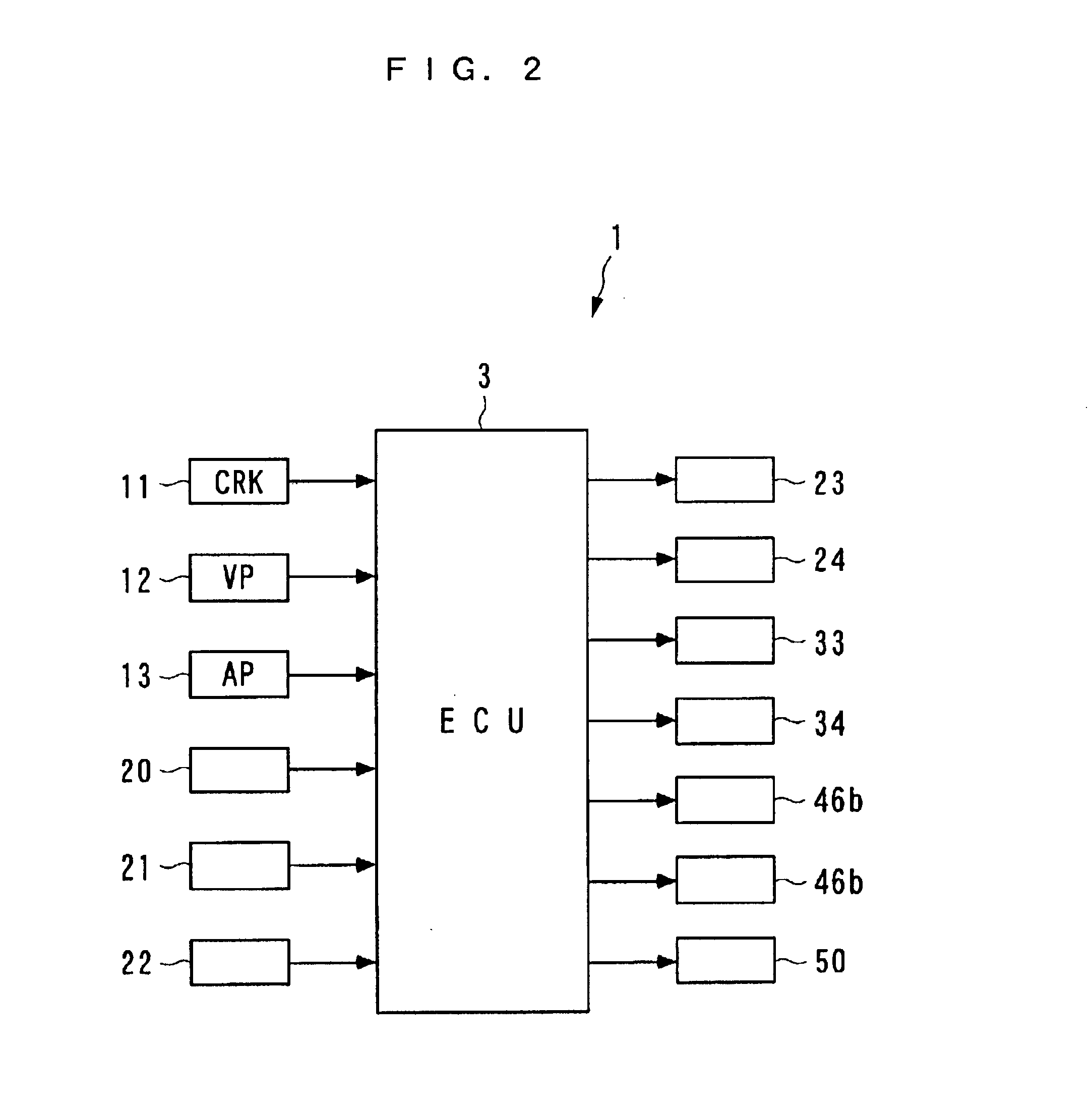
In the following, a preferred embodiment of the present invention will be described in detail with reference to the accompanying drawings. FIGS. 1 and 2 generally illustrate the configuration of a vehicle driving system to which a control apparatus 1 for a continuously variable transmission for use with a vehicle is applied according to the present invention. The control apparatus 1 controls a transmission ratio of a continuously variable transmission 40, and the like, as later described.

An internal combustion engine (hereinafter called the "engine") 2 is a gasoline engine equipped in a vehicle V. The engine 2 is coupled to driven wheels 7 through a fly wheel damper 4, an automatic transmission 5, a differential gear mechanism 6 and the like, so that a torque of the engine 2 is transmitted to the driven wheels 7 through these components 4-6.

The fly wheel damper 4 is coupled to a crank shaft 2a of the engine 2 for transmitting a torque of the engine 2 to the automatic transmission 5 ...


PUM


Abstract

A control apparatus for a continuously variable transmission for use with a vehicle is provided for permitting a driver to select one from three transmission modes for the continuously variable transmission, and providing an appropriate transmission ratio in accordance with a particular operating condition of a vehicle without causing an insufficient engine torque or over-revolution, particularly when the transmission is switched from a continuously variable transmission mode to a stepped manual transmission mode. The control apparatus comprises an ECU and an MT switch. The ECU executes a continuous automatic transmission mode for continuously setting a transmission ratio of the continuously variable transmission in accordance with a detected operating condition of the vehicle. The ECU also executes a stepped automatic transmission mode for setting the transmission ratio of the continuously variable transmission to one of a plurality of predetermined transmission stages in accordance with the detected operating condition of the vehicle. The CPU further executes a stepped manual transmission mode for setting the transmission ratio to one of a plurality of predetermined transmission stages in accordance with a driver's intention of transmission. The ECU sets the continuously variable transmission to one of the continuous automatic transmission mode, the stepped automatic transmission mode and the stepped manual transmission mode in accordance with a manipulating state of an MT switch.

Description

1. Field of the InventionThe present invention relates to a control apparatus for continuously variable transmission for use with a vehicle which can continuously vary the output of an internal combustion engine.2. Description of the Prior ArtA conventional control apparatus for a continuously variable transmission of the type mentioned above is known, for example, from Japanese Patent No. 3,218,962. This continuously variable transmission is applied to an internal combustion engine equipped in a vehicle. The control apparatus provides an automatic transmission mode and a manual mode for the continuously variable transmission. In the automatic transmission mode, the transmission is controlled to continuously change the transmission ratio thereof to a target transmission ratio which is continuously set in accordance with a vehicle speed and the like. In the manual mode, on the other hand, one of a plurality of transmission stages is selected in accordance with an operation performed ...

Claims


Application Information

Patent Timeline
Patent Type & Authority Patents(United States)
IPC IPC(8): F16H61/662F16H61/66F16H61/16F16H61/04
CPCF16H61/66259F16H61/16Y10T477/6237F16H2061/6616Y10T477/6217F16H2061/6615
Inventor AOKI, AKIHIRAFUJIMOTO, SHUICHIKUNII, HISASHI
Owner HONDA MOTOR CO LTD
Learn More