Automatic transmission and method of preventing over-revolution of the same

a technology of automatic transmission and control method, which is applied in the direction of transportation and packaging, instruments, etc., can solve the problems of increasing the overall weight and the size of the automatic transmission, and achieve the effect of preventing over-revolution

Active Publication Date: 2011-03-08
JATCO LTD +1
View PDF46 Cites 0 Cited by
  • Summary
  • Abstract
  • Description
  • Claims
  • Application Information

AI Technical Summary

Benefits of technology

[0004]Thus, it is considered to give a sufficient strength for enduring an estimated speed to the rotational element assumed to rotate at high speed in case of a malfunction of the frictional element. However, increase in the strength of the rotational element results in increase in the overall weight and the size of the automatic transmission.
[0005]It is accordingly an object of the present invention to provide an automatic transmission adapted to prevent rotational speeds of rotational elements from increasing beyond a predetermined value even in case of a malfunction of some frictional element for thereby assuring protection of the transmission against damage without increasing the weight and size.
[0006]It is a further object of the present invention to provide a method of preventing over-revolution of an automatic transmission.
[0009]According to a further aspect of the present invention, there is provided a method for preventing over-revolution of an automatic transmission including a plurality of planetary gears disposed between an input shaft and an output shaft and having a plurality of rotational elements, and a plurality of frictional elements selectively engaged and released for controlling rotations and connections of the plurality of rotational elements in accordance with instructions so as to realize a plurality of gear positions, the method comprising detecting a rotational speed of a predetermined one of the plurality of rotational elements, other than the input shaft and the output shaft, and releasing all of the plurality of frictional elements when it is judged that the rotational speed of the predetermined one of the plurality of rotational elements is higher than a predetermined rotational speed.

Problems solved by technology

However, increase in the strength of the rotational element results in increase in the overall weight and the size of the automatic transmission.

Method used


Image

  • Automatic transmission and method of preventing over-revolution of the same
  • Automatic transmission and method of preventing over-revolution of the same
  • Automatic transmission and method of preventing over-revolution of the same

Examples


first embodiment

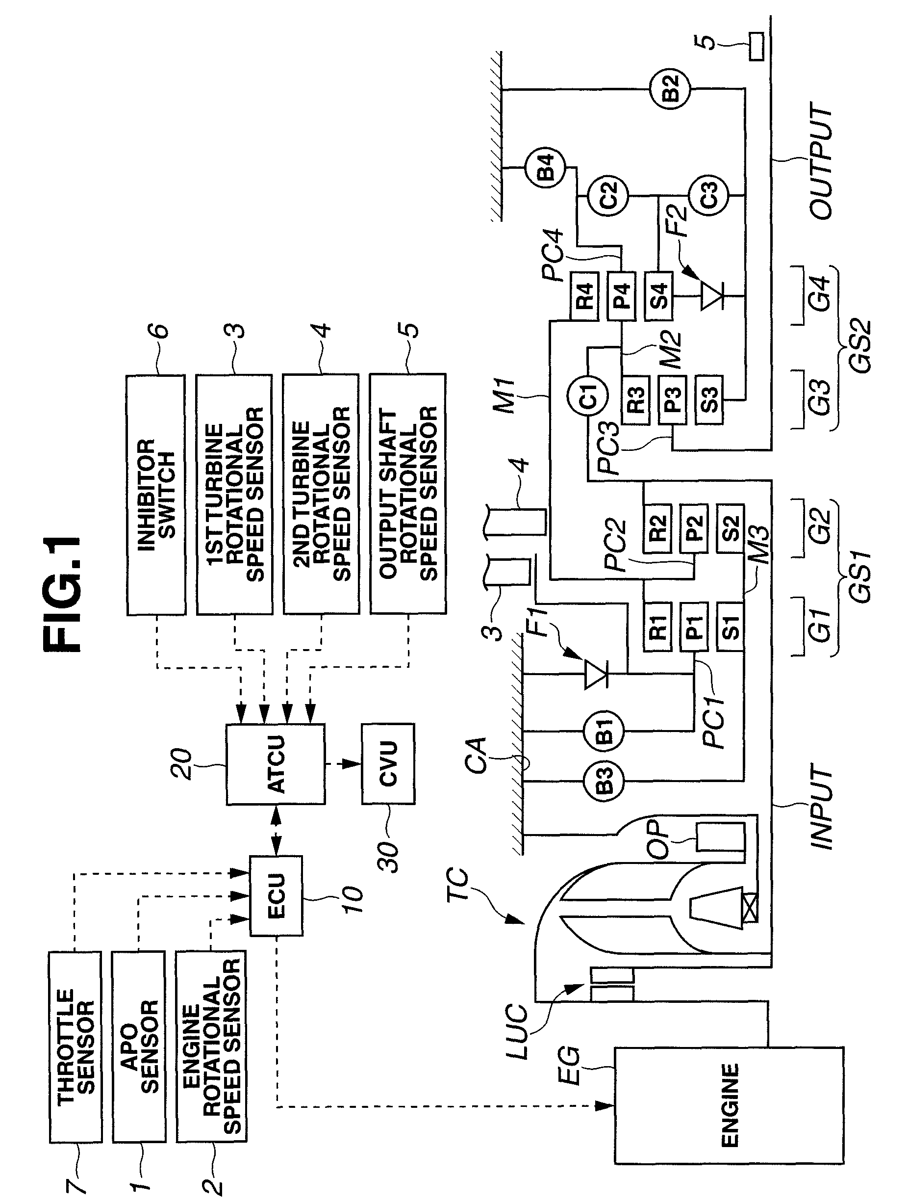
[0018]Referring first to FIG. 1, an automatic transmission is a stepped automatic transmission that provides seven forward speeds and one rearward speed. The driving force of an engine EG is supplied to an input shaft INPUT of the transmission by way of a torque converter TC and outputted from an output shaft OUTPUT after subjected to a change in speed by means of four planetary gears and nine frictional elements. Further, an oil pump OP is disposed coaxially with an pump impeller of the torque converter TC and driven to rotate by means of an engine EG to pressurize oil.

[0019]Further, there are provided an engine control unit (ECU) 10 for controlling an operating condition of the engine EG, an automatic transmission control unit (ATCU) 20 for controlling a shift state and so on of the automatic transmission, and a control valve unit (CVU) for controlling an oil pressure for each frictional element on the basis of an output signal of the ATCU 20. In the meantime, the ECU 10 and ATCU...

second embodiment

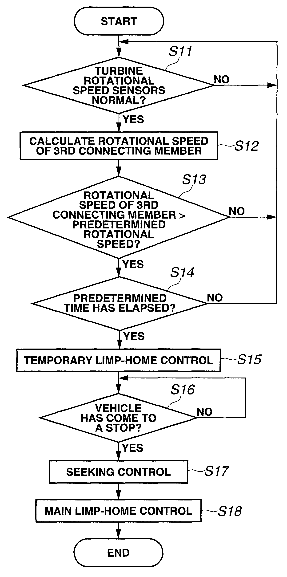
[0087]Then, the control executed in the ATCU 20 will be described with reference to FIG. 8 which shows a flowchart of a control for preventing over-revolution of the automatic transmission according to the

[0088]Step S21 is the same as step S11 of the first embodiment.

[0089]In step S22 (rotational speed detecting section or means), the rotational speed of the third connecting member M3 that is detected by the third turbine speed sensor 3A is read. In the meantime, in this embodiment, the rotational speed of the third connecting member 3A is detected directly so that its estimation is not necessitated.

[0090]In step S23, it is determined whether the rotational speed of the third connecting member M3 that is detected by the third turbine speed sensor 3A is higher than a predetermined speed. If the rotational speed of the third connecting member M3 is higher than the predetermined speed, the control proceeds to step S24, and if equal to or lower than the predetermined speed, the control ...


PUM


Abstract

An automatic transmission includes a plurality of planetary gears disposed between an input shaft and an output shaft and having a plurality of rotational elements. A plurality of frictional elements are selectively engaged and released for controlling rotations and connections of the plurality of rotational elements in accordance with instructions so as to realize a plurality of gear positions. A rotational speed detecting section detects a rotational speed of a predetermined one of the plurality of rotational elements other than the input shaft and the output shaft. A frictional element release section releases all of the plurality of frictional elements when it is judged that the rotational speed of the predetermined one of the plurality of rotational elements is higher than a predetermined rotational speed.

Description

BACKGROUND OF THE INVENTION[0001]The present invention relates to a control for preventing over-revolution of rotational elements in a multi-speed automatic transmission. More specifically, the present invention relates to an automatic transmission adapted to prevent such over-revolution and a method for carrying out such a control.[0002]There is disclosed in Unexamined Japanese Patent Publication No. 9-89098 a technique for preventing, when increase of an engine speed beyond a predetermined value occurs in a vehicle having installed thereon an automatic transmission, further increase of the engine speed by upshifting for thereby protecting the engine against damage.SUMMARY OF THE INVENTION[0003]In the event of a malfunction of an automatic transmission frictional element, particularly, a release malfunction of the same, there may occur such a case where a rotational element other than an input shaft is increased in speed in accordance with a tooth ratio of a planetary gear set so a...

Claims


Application Information

Patent Timeline
Patent Type & Authority Patents(United States)
IPC IPC(8): F16H31/00F16H59/42F16H59/46F16H61/02F16H61/16F16H61/68F16H61/684F16H61/686
CPCF16H61/12F16H61/686F16H2059/385F16H2200/2053F16H2200/0056F16H2200/2012F16H2061/1208F16H61/18F16H61/16F16H61/00
Inventor KAWAGUCHI, TAKATERUMOCHIYAMA, SHINYANAGASHIMA, FUMITAKASHINSO, YOSHIHIDE
Owner JATCO LTD
Why Eureka
Try Eureka