Die molding machine and pattern carrier

a technology of pattern carrier and molding machine, which is applied in the direction of molding machine, manufacturing tools,foundry moulding apparatus, etc., can solve the problems of high cost, large amount of sand generated by related facilities, and high height of molding machine used for them, so as to reduce the generation of spills or scraps of sand, the effect of low cost and easy replacemen

Inactive Publication Date: 2004-11-30
SINTOKOGIO LTD
View PDF5 Cites 2 Cited by
  • Summary
  • Abstract
  • Description
  • Claims
  • Application Information

AI Technical Summary

Benefits of technology

In accordance with the first embodiment of this invention, without the need to install large scale oil cylinders for lifting a pattern plate such as one requiring a pit, almost all the foundry sand in a molding space defined by a pattern plate and molding flask can be surely compressed into a mold having a desired hardness.In accordance with the second embodiment of this invention, wherein a two step squeeze compression and an increase in the accuracy of removing a flask have been achieved, since the generation of spilled sand and chips of sand is greatly reduced, the molding space can be quantitatively and effectively filled with foundry sand, and since foundry sand is squeezed in correspondence to the concave / convex shape of a pattern plate, a homogenous mold can be molded. Further, since the power of the working fluid and the consumption of compressed air can be reduced, a reduction in cost is realized by saving energy.In accordance with the pattern carrier of this invention, with the adoption of a flask-removing frame the body of the molding machine is simplified, and since flask-removing cylinders can also be used for both the upper and lower pattern carrier installed in both ends of the pattern replacing device, the simple structure of this invention enables the number of actuators to be halved, to save the power of working fluid.In accordance with the embodiment of the improved pattern plate carrier of this invention, since the pattern plate carrier with an auxiliary flask can be compact, and since the time and labor for the attachment / detachment of piping can be reduced, the pattern plate carrier with an auxiliary flask can be accurately and movably installed.As is clear from the above descriptions, the pattern plate carrier molding machine of this invention has various, excellent practical effects.

Problems solved by technology

This method has some problems in that since it needs large-sized cylinders the height of a molding machine used for them becomes high and the related facilities, such as a pit, cost a lot accordingly.
This method has also some disadvantages in that since in it, wherein an auxiliary flask on which a molding flask is put is put on the upper part of a pattern plate, the foundry sand thrown into the molding space to fill it must be smoothed prior to compression, so that a lot of spilled sand may be generated, and so that uneven compression or an uneven compressed surface may occur.
Therefore, a lot of time and labor are needed to deal with such disadvantages.
Further, there is also a problem in that to remove the piping of the air cylinder the replacement of the pattern plate carrier with an auxiliary flask is very troublesome.

Method used


Image

  • Die molding machine and pattern carrier
  • Die molding machine and pattern carrier
  • Die molding machine and pattern carrier

Examples


first embodiment

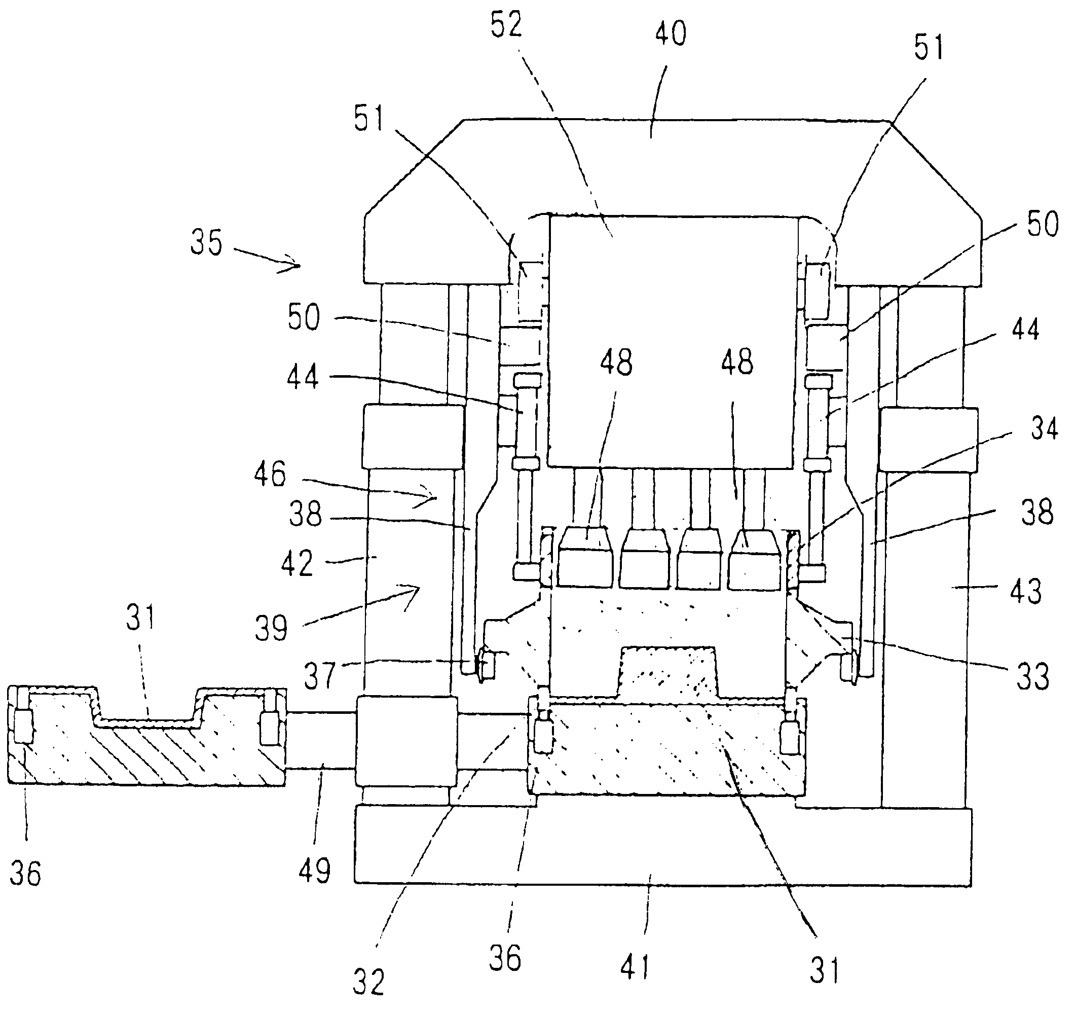
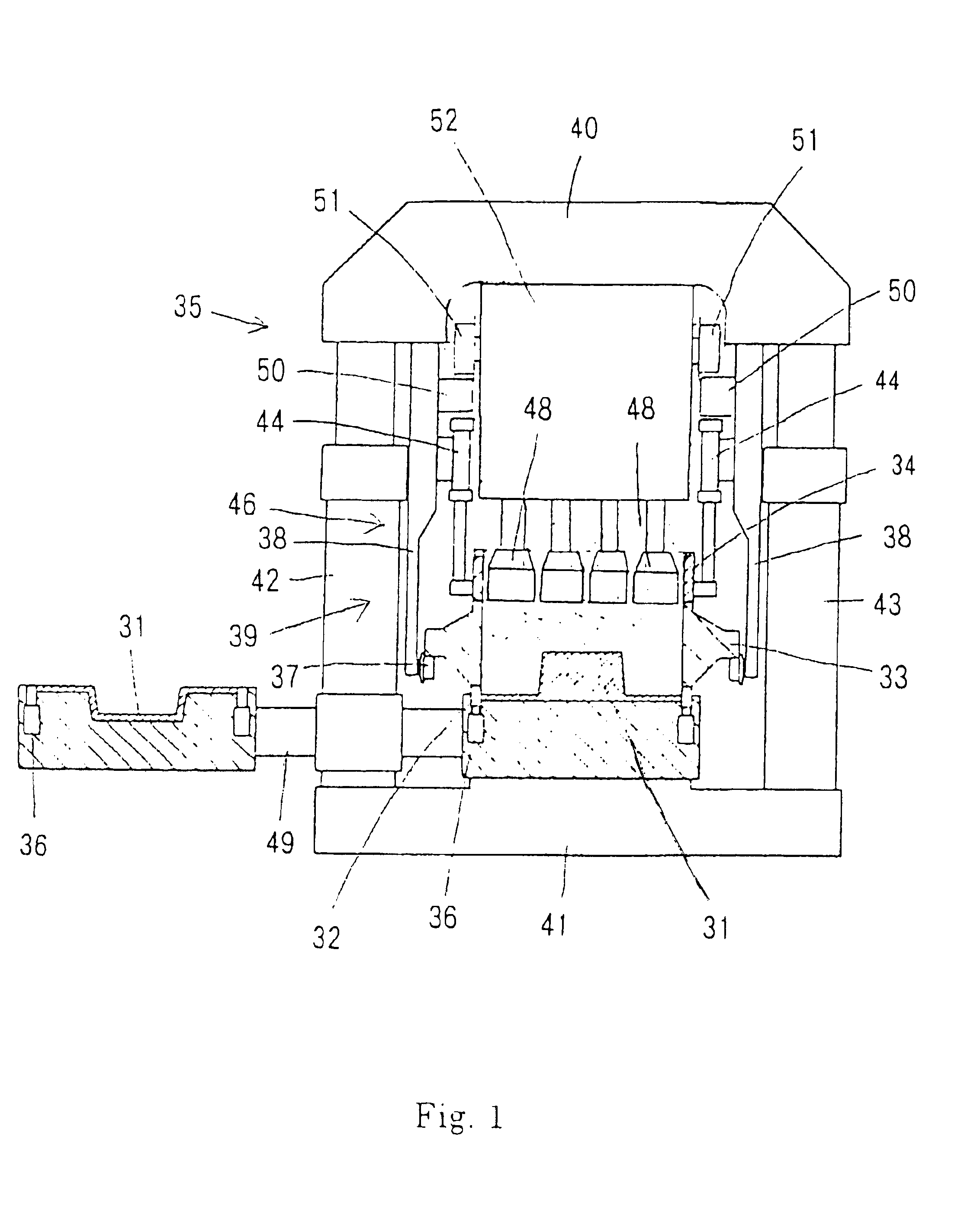
Referring to FIG. 1, now we explain the molding machine of this invention. The molding machine comprises a pattern plate 31 fixed horizontally, a lower subsidiary flask 32 that surrounds the periphery of the pattern plate 31 and that is disposed such that it can be both slid and moved up and down, a molding flask 33 that is disposed above the lower subsidiary flask 32 so as to be moved up and down, an upper subsidiary flask 34 disposed above the molding flask 33 so as to be moved up and down, and the squeeze feet 48 of the compressing means 35, which are disposed so as to be movable up and down above the molding flask 33 such that their ends can reach within an area surrounded by the upper subsidiary flask 34.

The pattern plate 31 is mounted on the upper surface of a turntable 49, described below. In the upper surface of the pattern plate 31, vent-plugs (not shown) are embedded according to the shape of the pattern plate. The lower subsidiary flask 32, mounted on the turntable 49, is...

second embodiment

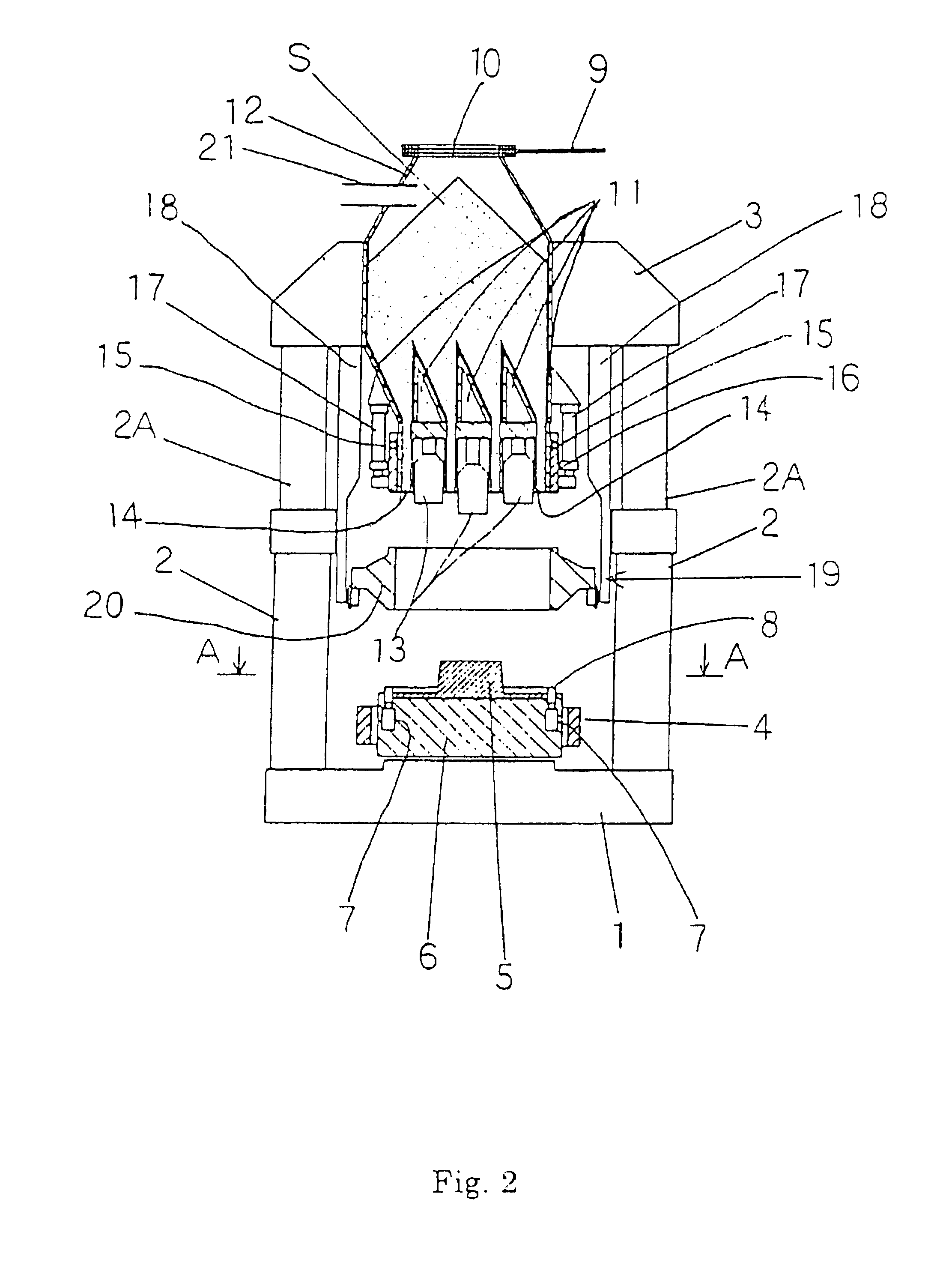
Now we explain this invention by referring to FIGS. 2-10.

In FIG. 2, upward flask-setting cylinders 2,2 are mounted on a molding base 1, and a frame 3 for supporting the lifting movement of molding members bridges the rods 2A,2A of the cylinders 2,2. A pattern-replacing device 4 for alternatively transporting a pattern carrier 6,6A (see FIG. 9), on which a pattern plate 5,5A is to be mounted, is disposed above the molding base 1 in a direction perpendicular to the left and right directions of the flask-setting cylinders 2,2. The pattern-replacing device 4 is disposed so as to be movable perpendicular to the face of the drawing by an actuator (not shown).

A pattern carrier 6,6A, on which a pattern plate 5,5A (an upper and lower pattern plates) is to be mounted; is mounted on both sides of the pattern-replacing device 4 such that the pattern carrier 6,6A is in a raised state by about 5 mm through a spring (not shown), and such that the pattern plate 5,5A is alternatively transported int...


PUM

PropertyMeasurementUnit
moldingaaaaaaaaaa
heightaaaaaaaaaa
timeaaaaaaaaaa

Abstract

A pattern carrier for a flask molding machine including a mount on which a pattern plate is mounted and a flask-shaped, molding flask-removing frame adapted to make contact with a lower end of a molding flask of a flask molding machine and moveable up and down around said pattern plate for removing a finished mold.

Description

This invention relates to a method and apparatus for compressing foundry sand in a molding space. It also relates to a molding machine equipped with a flask and a pattern carrier, wherein upper and lower mold halves are alternately molded for each empty mold half carried therein. In particular, it relates to improvement in the pattern plate carrier with an auxiliary flask carried along with a pattern plate.Conventionally, foundry sand has been compressed in a molding space formed between a pattern plate and molding flask by having the pattern plate and compressing means approach each other. This method has some problems in that since it needs large-sized cylinders the height of a molding machine used for them becomes high and the related facilities, such as a pit, cost a lot accordingly. This method has also some disadvantages in that since in it, wherein an auxiliary flask on which a molding flask is put is put on the upper part of a pattern plate, the foundry sand thrown into the ...

Claims


Application Information

Patent Timeline
Patent Type & Authority Patents(United States)
IPC IPC(8): B22C15/00B22C15/06B22C15/08B22C15/34
CPCB22C15/08B22C15/06
Inventor KANETO, KIMIKAZUHIRATA, MINORUHADANO, YUTAKA
Owner SINTOKOGIO LTD
Why Eureka
Try Eureka