Method and system for forming an object proxy

a proxy and object technology, applied in the field of computer graphics, can solve the problems of increasing the number of calculations and other processing work required to render the object, increasing the number of computations and other processing work, and speed and cos

Inactive Publication Date: 2004-12-14
RPX CORP +1
View PDF2 Cites 18 Cited by
  • Summary
  • Abstract
  • Description
  • Claims
  • Application Information

AI Technical Summary

Benefits of technology

The present invention has general application as it can be used to form object proxies for all types of object shapes. The present invention also forms an object proxy that approximates object geometry and reduces the processing work required at run-time. For example, the object proxy can have less polygons and associated vertices than the original object. In this way, rendering of the object based on the object proxy can be carried out for display or animation in real-time at an interactive rate even on cheaper graphics hardware. Compared to a general mesh simplification algorithm, object proxies formed according to the present invention are assured to have no or minimal interaction with an object, which is especially advantageous in hardware-accelerated image-based rendering.
Another advantage is that present invention allows object formation parameters to be user-specified (or set by default) so that the degree in which the isosurface shape approximates the original object surface can be adjusted depending upon a particular application or need. Forming object proxies according to the present invention also make it possible both to render more image-based objects in a single computer generated scene and to render these image-based objects using fewer views / textures than conventional image-based rendering schemes.

Problems solved by technology

These demands include realism, speed and cost.
Complex objects, however, can involve a large number of primitives.
This increases the number of calculations and other processing work required to render the object.
Conventional approaches to forming an object proxy, however, have been limited.
The progressive hull approach described in the Buehler and Sander articles has significant deficiencies.
This progressive hull approach cannot handle concave proxies, or objects that have parts close to each other or touching each other.
In addition, this approach is not well suited for mixing image-based rendering (ibr) objects with regular scenes.

Method used


Image

  • Method and system for forming an object proxy
  • Method and system for forming an object proxy
  • Method and system for forming an object proxy

Examples


example system embodiment

of the Present Invention

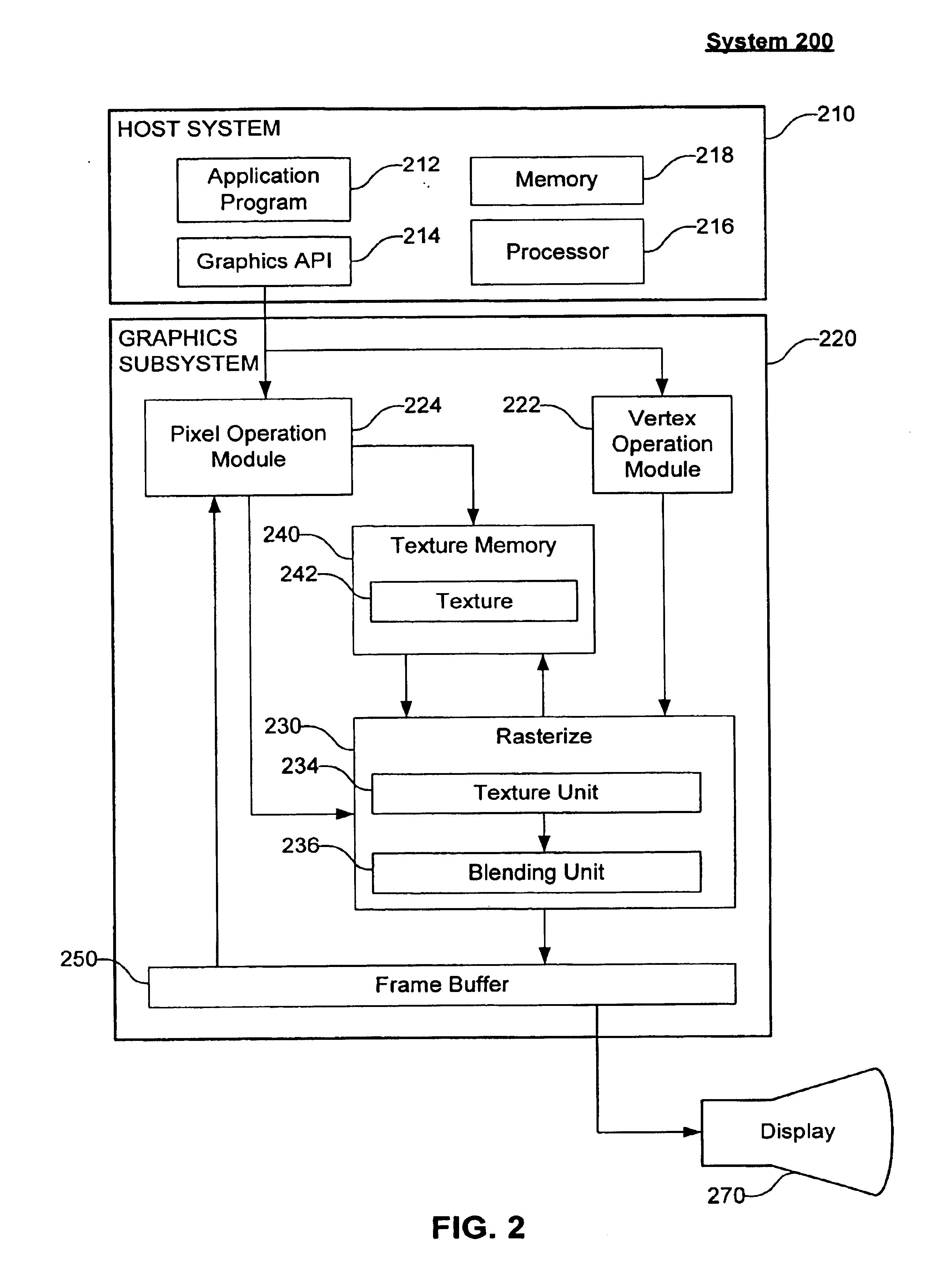
FIG. 2 illustrates an example graphics system 200 according to an embodiment of the present invention. Graphics system 200 comprises a host system 210, a graphics subsystem 220, and a display 270. Each of these features of graphics system 200 is further described below.

Host system 210 comprises an application program 212, a hardware interface or graphics API 214, a processor 216, and a memory 218. Application program 212 can be any program requiring the rendering of a computer image. The computer code of application program 212 is executed by processor 216. Application program 212 assesses the features of graphics subsystem 220 and display 270 through hardware interface or graphics API 214. Memory 218 stores information used by application program 212.

Graphics subsystem 220 comprises a vertex operation module 222, a pixel operation module 224, a rasterizer 230, a texture memory 240, and a frame buffer 250. Texture memory 240 can store one or more textures or ...

example method embodiments

of the Present Invention

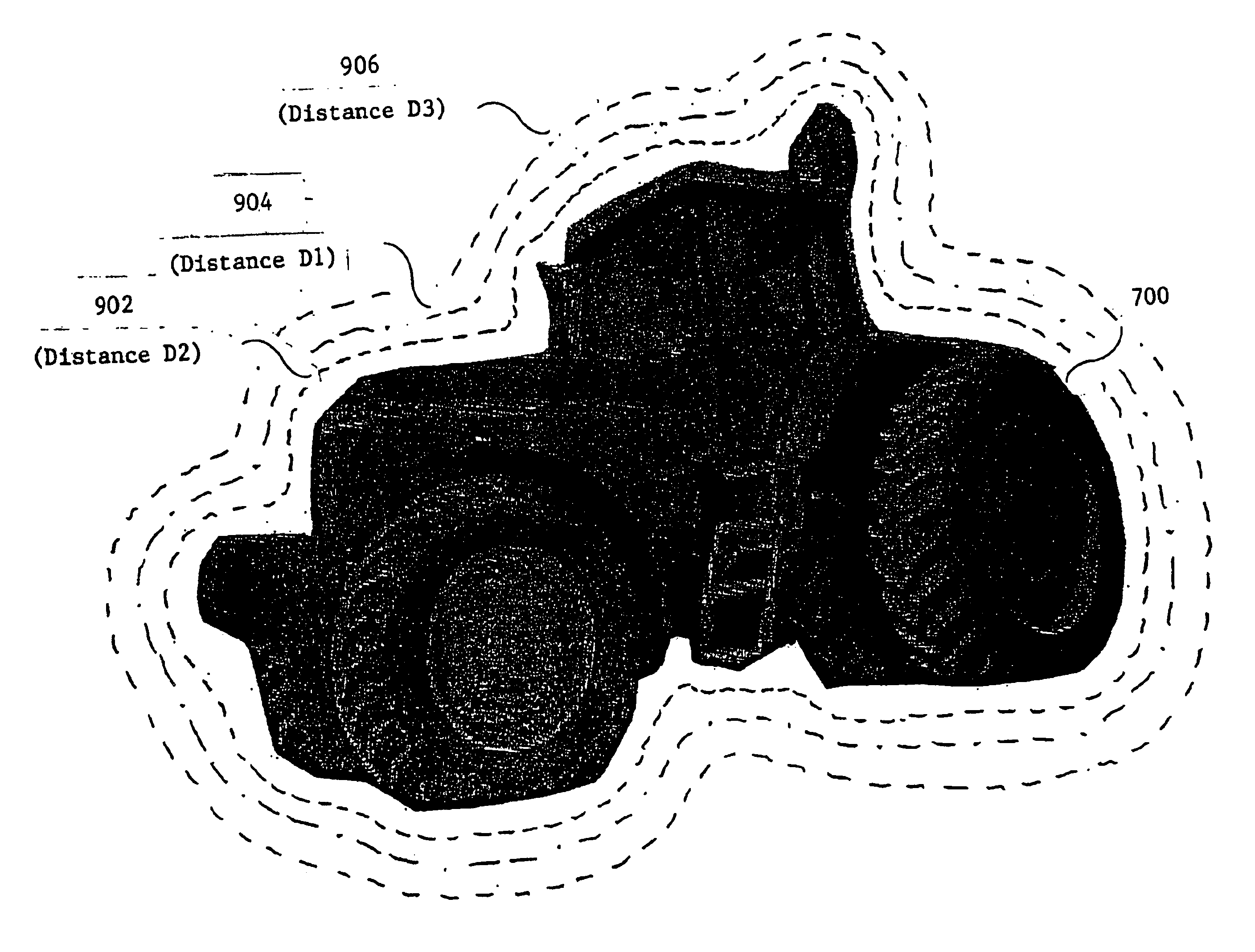
FIGS. 3A-3B illustrate a flowchart of the steps of a method 300 for forming an object proxy according to an embodiment of the invention. As noted above, an object proxy is a simplification of an object boundary that is useful for hardware-accelerated image-based rendering. Object proxies according to the present invention make it possible both to render more image-based objects in a single computer generated scene and to render these image-based objects using fewer views / textures than a conventional image-based rendering scheme.

In an embodiment, method 300 operates as follows. At least one object proxy formation parameter is specified. Using one or more of the specified formation parameters, a volume / grid is constructed around an object whose proxy is to be formed. An isosurface is created at a nominal distance D1 from the object's surface using a marching cubes algorithm on the volume / grid. In embodiments, an optional step is used to detect voxels of the vol...


PUM


Abstract

A system, method and computer program product for forming an object proxy. In one embodiment, a method forms an object proxy that approximates the geometry of an object. The method includes forming a volume that encompasses the object, forming an isosurface within the volume, adjusting the isosurface relative to a surface of the object, and pruning the isosurface to obtain the object proxy. An apparatus includes an isosurface former that forms an isosurface within a volume encompassing an object, and an isosurface shaper that adjusts the isosurface relative to the surface of the object and prunes the isosurface to obtain the object proxy.

Description

1. Field of the InventionThe present invention relates to computer graphics.2. Related ArtA wide variety of applications rely on computer graphics to generate images. An image is made up of an array of picture elements (pixels) and can be displayed on a display unit, such as, a monitor, screen, or cathode ray tube. Images often include graphical representations of objects. Many different types of computing devices with graphics capabilities are used to generate images. Such computing devices use graphics processing. A combination of software, firmware and / or hardware is used to implement graphics processing. For example, graphics processing including rendering can be carried out in a graphics card, graphics subsystem, graphics processor, graphics or rendering pipeline, and / or a graphics application programming interface (API) and libraries, such as, OPENGL.In computer graphics, the geometry of an object is represented by primitives. Common primitives are points, lines, and polygons ...

Claims


Application Information

Patent Timeline
Patent Type & Authority Patents(United States)
IPC IPC(8): G06T17/10
CPCG06T17/10
Inventor MECH, RADOMIR
Owner RPX CORP
Why Eureka
Try Eureka