Drawer support and closure apparatus

a technology for supporting and closing drawers, which is applied in the direction of drawers, furniture parts, domestic applications, etc., can solve the problems of high price of the type of drawer slide used in conventional drawer slide models

Inactive Publication Date: 2005-01-04
GRASS AMERICA
View PDF13 Cites 15 Cited by
  • Summary
  • Abstract
  • Description
  • Claims
  • Application Information

AI Technical Summary

Problems solved by technology

Apparatus of the type used in conventional drawer slides is expensive in that these devices are usually formed of m

Method used


Image

  • Drawer support and closure apparatus
  • Drawer support and closure apparatus
  • Drawer support and closure apparatus

Examples


Embodiment Construction

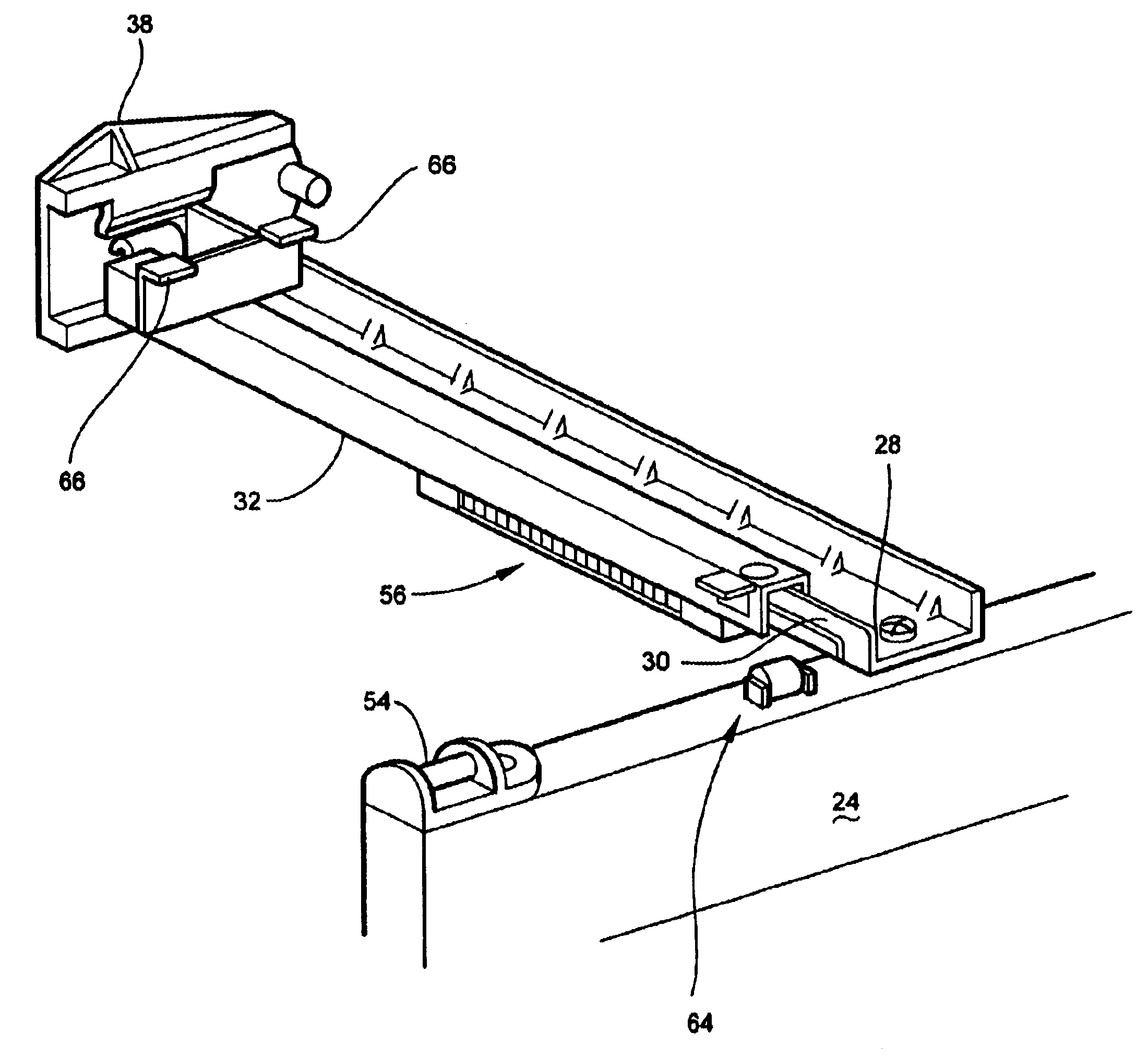
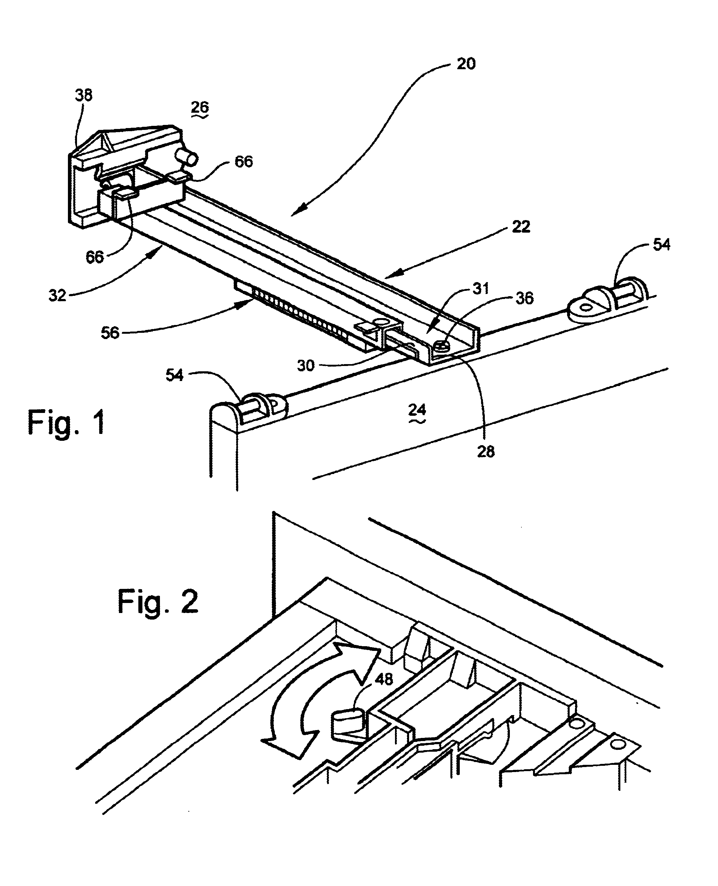
Referring now to the drawings and particularly to FIG. 1, the drawer support and closure apparatus of the present invention is shown generally as 20 and includes a drawer support member 22 connecting the supporting frame front 24 and back 26. Support member 22 has an upstanding segment 28 and a ridge 30 formed therewith also referred to as a guide rail and shown generally as 31. All of these components are formed integrally with support member 22 preferably in a metal stamping operation.

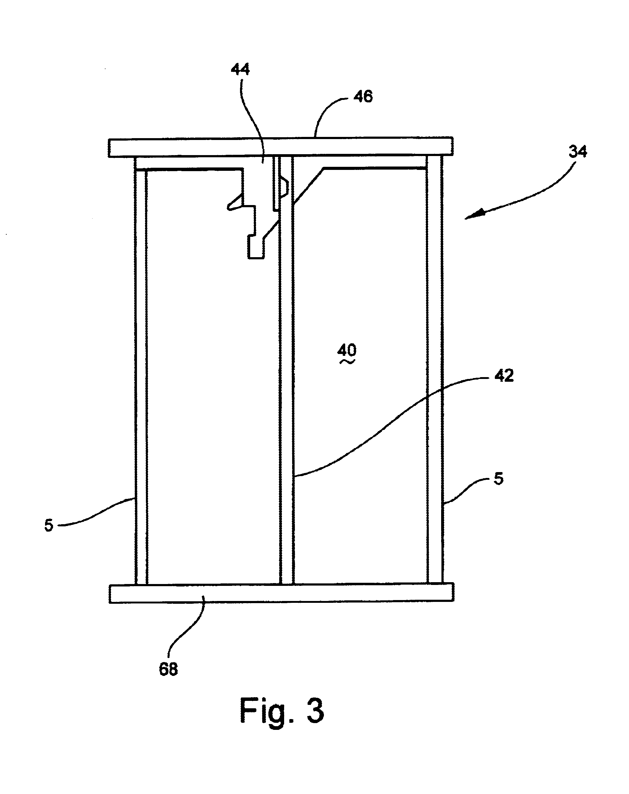
A ridge-surrounding member 32 cooperatively receives ridge 30 of guide rail 31 in close proximity to upstanding segment 28 and is movable with respect to guide rail 31. Ridge-surrounding member 32 is connected to the bottom or floor of an associated drawer shown generally as 34 (FIG. 3) and has four (4) linear interior walls 35 (FIG. 10).

The forward end of support member 22 is affixed to door frame front 24 by a screw 36 or some other appropriate fastening device. The trailing end of support member 2...


PUM


Abstract

A drawer slide support and closure apparatus designed to support a drawer within its supporting frame includes one or more drawer support members connecting the frame front and back each of which has an upstanding member with a ridge formed therewith forming a guide rail. A ridge surrounding slidable member encompasses the guide rail and is movable with respect to it. The ridge surrounding member is affixed to the bottom of the drawer and enables slidable movement between the guide rail supported by the frame and the ridge surrounding member affixed to the drawer. Rollers provide additional support for the drawer in the open position, and a spring enables positive opening and closing of the drawer. A shock absorber minimizes sound and impact when the drawer is firmly closed.

Description

BACKGROUND OF THE INVENTION1. Field of the InventionThe present invention relates to drawer supporting and closing mechanisms and more particularly for a drawer slide support and closure apparatus that enables one or more drawer support members to facilitate slidably openable and closeable drawers within a frame.2. Description of the Prior ArtSlidable drawer opening and closing devices are well known and conventionally utilize a pair of supporting and slidably connected guide rails and rail engaging slides to support the drawer within its frame and allow for openable and closeable slidable movement therein. Apparatus of the type used in conventional drawer slides is expensive in that these devices are usually formed of metal, attached to the inner side of the frame by a large profile limb and, require two units in each drawer setting.Many attempts have been made to reduce the cost of these devices by reducing the amount of metal incorporated in each, replacing certain elements with ...

Claims


Application Information

Patent Timeline
IPC IPC(8): A47B88/04A47B88/14
CPCA47B88/047A47B88/14A47B2210/0056A47B2210/0005A47B88/467A47B88/477A47B2210/0037A47B88/487
Inventor DOMENIG, GEORG
Owner GRASS AMERICA
Why Eureka
Try Eureka