Demultiplexer for optical time-division multiplexed signals

Inactive Publication Date: 2005-01-04
ALCATEL LUCENT SAS
View PDF7 Cites 0 Cited by
  • Summary
  • Abstract
  • Description
  • Claims
  • Application Information

AI Technical Summary

Benefits of technology

It is, therefore, an object of the present invention to provide a demultiplexer for an OTDM digital signal a

Problems solved by technology

On a receiver side, an optical demultiplexer usually de-interleaves the channels, because electronic devices are not capable of directly processing signals with bit rates BM.
In ultra-high-speed OTDM transmission systems having bit rates of more than 40 Gbit/s, pulse durations are extremely short.
Such extremely short pulse durations pose very high demands on demultiplexers that are one of the key components in OTDM transmission systems.
Demultiplexers that are capable of separating pulses in ultra-high bit rate optical transmission systems require very short time windows, a high extinction ratio and a weak polarization dependence.
These devices, however,

Method used


Image

  • Demultiplexer for optical time-division multiplexed signals
  • Demultiplexer for optical time-division multiplexed signals
  • Demultiplexer for optical time-division multiplexed signals

Examples


Example

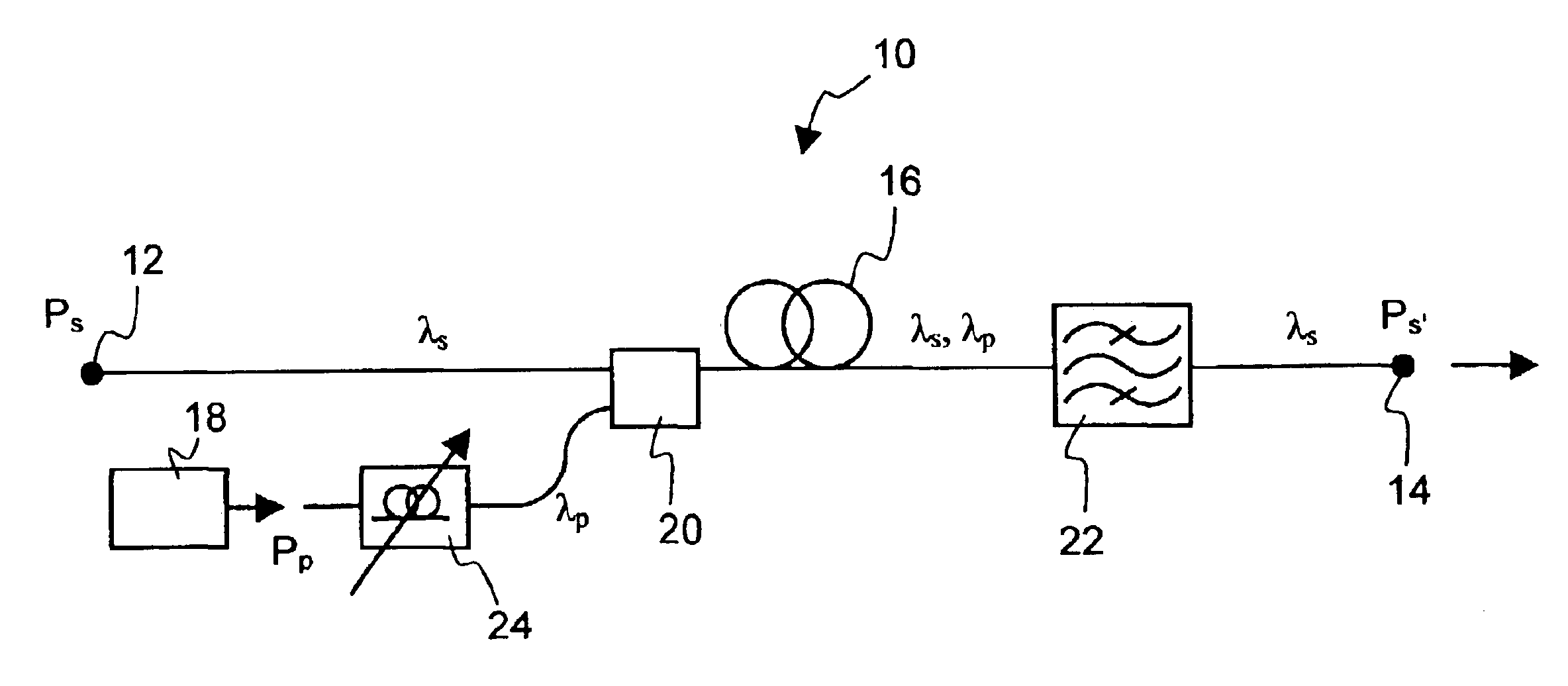
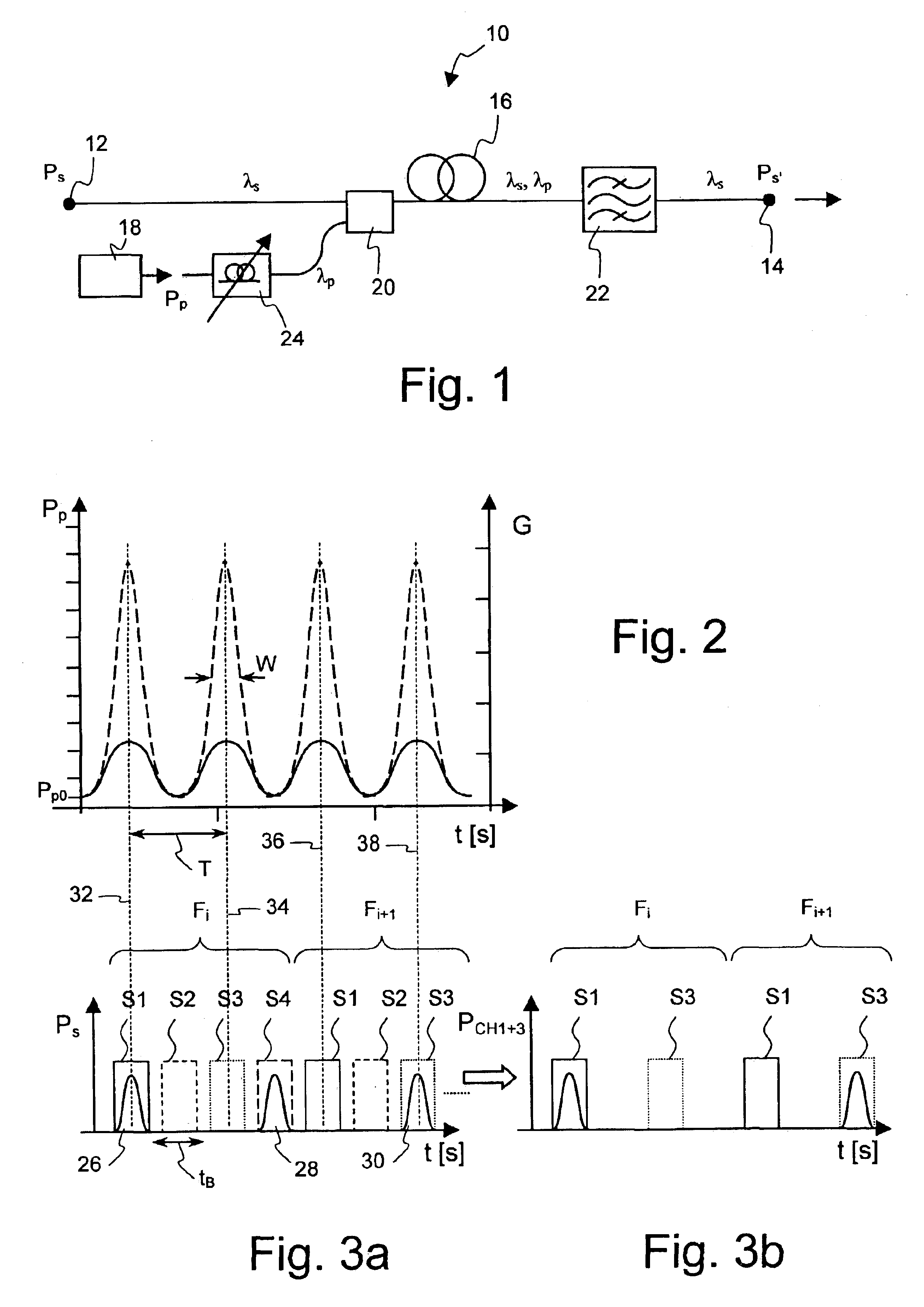
FIG. 1 schematically depicts a first exemplary embodiment of a demultiplexer according to the present invention, being designated in its entirety by 10. Demultiplexer 10 comprises an optical input 12 in which an optical time-division multiplexed (OTDM) digital signal Ps having a signal wavelength λs and a bit rate B can be coupled into. Demultiplexer 10 further comprises an optical output 14 at which a demultiplexed optical signal Ps′ of wavelength λs may be coupled into another optical component.

Between input 12 and output 14 a Raman active optical medium is disposed, which in this embodiment is a Raman active fiber 16 of the kind as used in Raman fiber amplifiers. The underlying physical principle of Raman amplification is the effect of stimulated Raman scattering. This is a non-linear optical process that occurs at high optical intensities and involves coupling of light propagating through the non-linear medium to vibrational modes of the medium. Amplification is caused by an ene...


PUM


Abstract

A demultiplexer for an optical time-division multiplexed digital signal, which has a signal wavelength λs and is transmitted with a bit rate B, is described. It comprises a Raman active optical medium, a pump source for generating a periodic optical pump signal having a pump wavelength λp and a periodicity of B/n where n is an integer ≧2, and a coupler for coupling the digital signal and the pump signal into the Raman active optical medium. The new demultiplexer exploits the non-linear Raman gain response of the Raman active medium to a high power pump signal and has a narrow time window and a high extinction ratio.

Description

The invention is based on a priority application EP 02 360 205.5 which is hereby incorporated by reference.BACKGROUND OF THE INVENTIONThe present invention relates to a demultiplexer for an optical time-division multiplexed (OTDM) digital signal that has a signal wavelength λs and is transmitted with a bit rate B. The invention further relates to a method for demultiplexing such a digital signal.In a typical OTDM system, an optical pulse source on the transmitter side generates a pulse train with a channel bit rate BC that equals the base rate of electronic data streams fed to the OTDM system. At present, the highest electronic base rate available is 40 Gbit / s. The optical pulse train generated by the pulse source is coupled into n optical branches in which modulators are driven by the electrical data streams. Each modulator imprints the incoming data stream on the pulse train, thereby generating an optical data signal with the channel bit rate BC. The n optical data signals, which ...

Claims


Application Information

Patent Timeline
IPC IPC(8): H04J14/08H04B10/17H04B10/291
CPCH04J14/08H04B10/2916
Inventor SEGUINEAU, FREDERICLECLERC, OLIVIER
Owner ALCATEL LUCENT SAS
Why Eureka
Try Eureka