Method and system for optical routing of variable-length packet data

a variable-length packet data and optical routing technology, applied in the field of optical communication networks, can solve the problems of limiting the overall bandwidth capacity of the network, limiting the amount of delay, and limiting the ring for delaying and buffering optical signals, so as to facilitate full optical routing of ip packets

Inactive Publication Date: 2005-01-04
BIOSPHERICS
View PDF8 Cites 64 Cited by
  • Summary
  • Abstract
  • Description
  • Claims
  • Application Information

AI Technical Summary

Benefits of technology

An advantage of the present invention is that it facilitates full optical routing of IP packets, which naturally vary widely in length, using optical routing equipment designed to accommodate fixed-length data packets.

Problems solved by technology

This solution suffers the disadvantage that within each node of the optical network, the IP packet must be converted from optical to electronic form and then back into optical form for transmission over the next link.
Thus, while the bandwidth capacity of each fiber link may be very high, the overall bandwidth capacity of the network is restricted by the speed and reliability of the electronic components of each node, and in particular the speed with which optical signals can be converted into electronic signals and buffered.
The use of a fiber ring for delaying and buffering optical signals suffers the disadvantage that the amount of delay is governed primarily by the length of the fiber ring (the time delay is equal to the length of the ring divided by the speed of light in the fiber medium of the ring).
If the defined maximum length is too large, unnecessarily long delays will be incurred as packets move through the node.
Alternatively, if the defined maximum length is too small, the available band-width of the network may be unnecessarily limited.

Method used


Image

  • Method and system for optical routing of variable-length packet data
  • Method and system for optical routing of variable-length packet data
  • Method and system for optical routing of variable-length packet data

Examples


Embodiment Construction

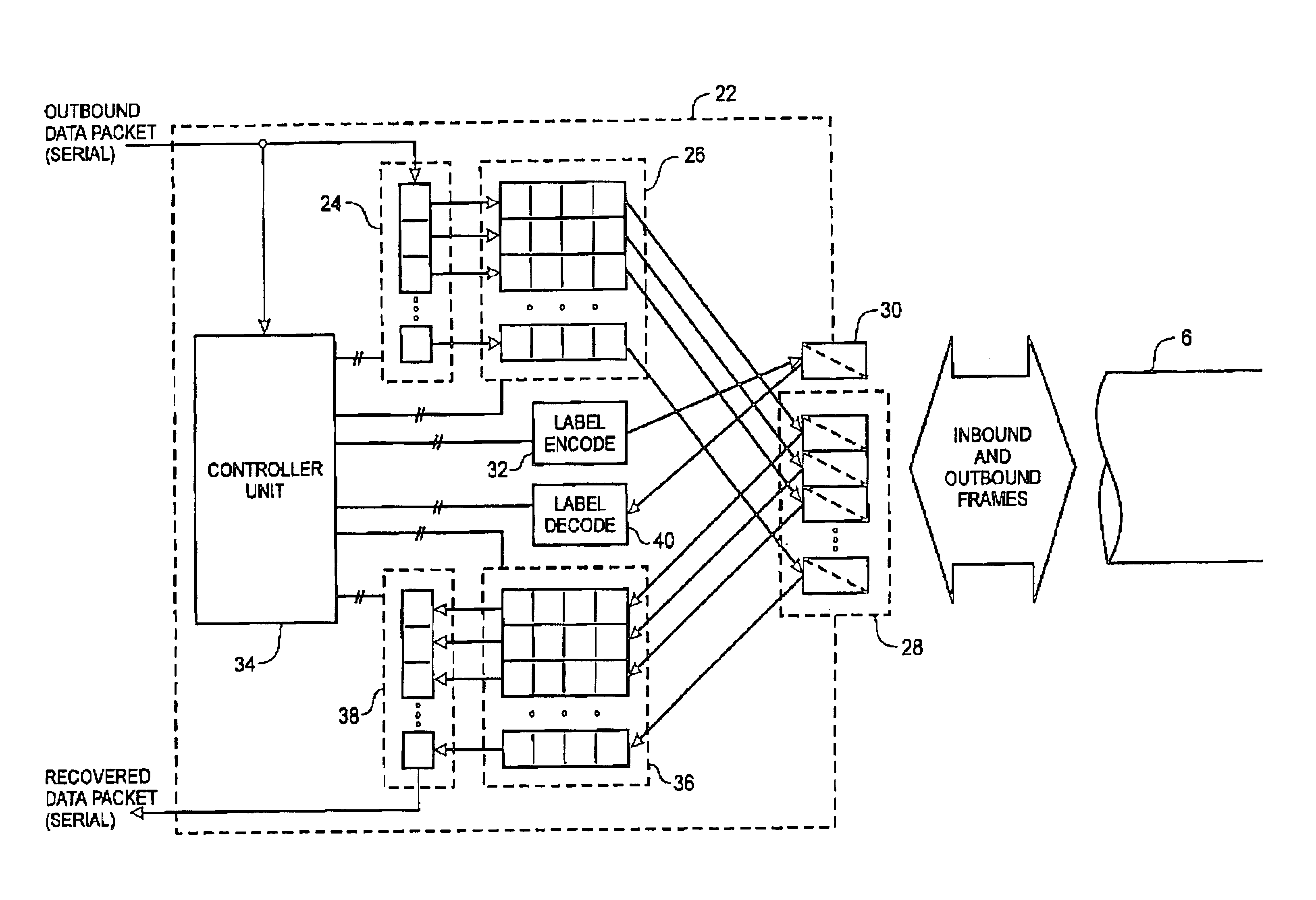
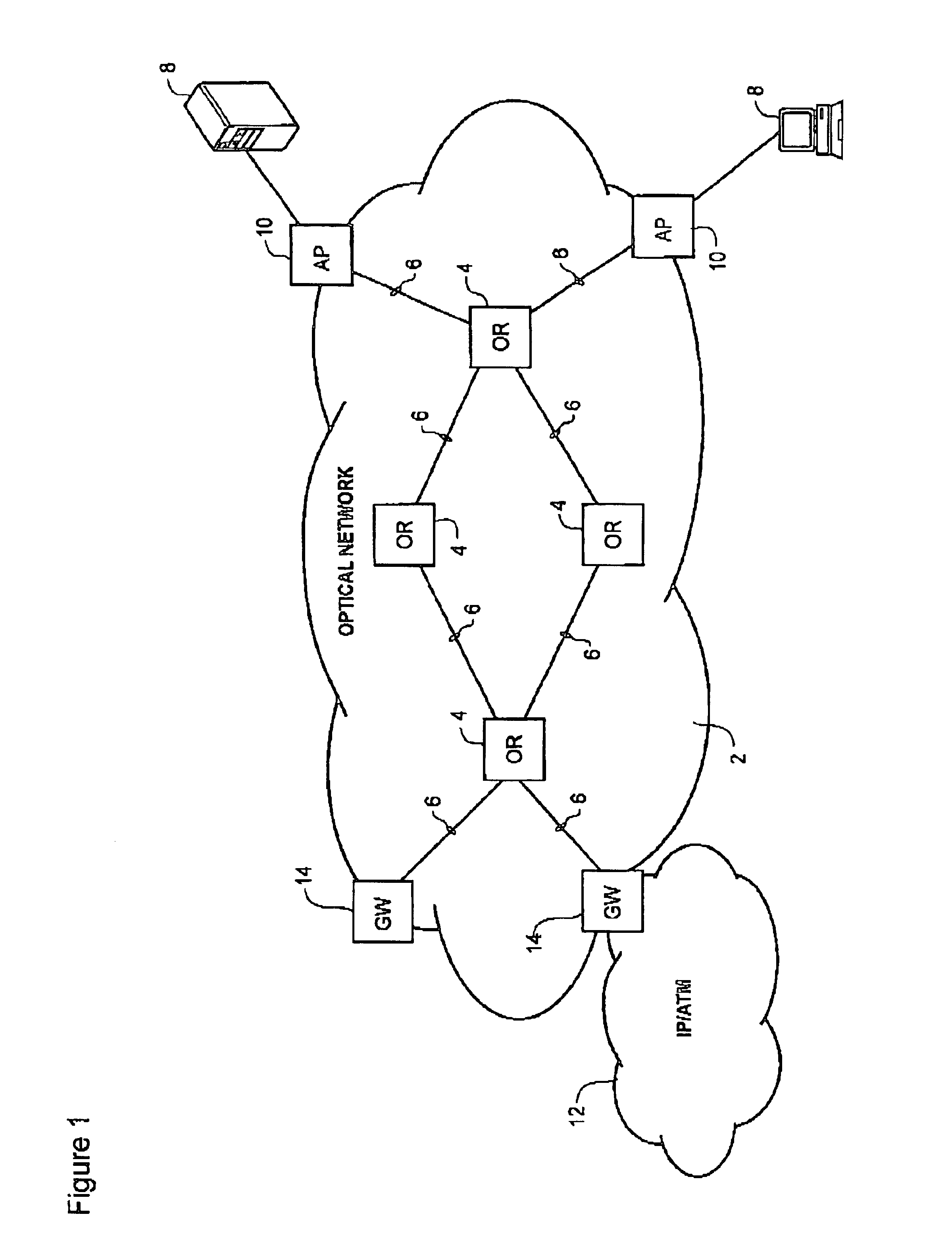
The present invention provides a system for fully optical routing of variable length packetized data traffic, for example internet protocol (IP) packets and / or asynchronous transfer mode (ATM) frames across an optical network. AS shown in FIG. 1, an optical network 2 usable in conjunction with the present invention generally comprises a plurality of optical routers 4 (four are shown in FIG. 1) interconnected by fiber optic links 6. Communications devices 8, for example end user personal computers (PCs) or local area network (LAN) servers may be connected to the optical network 2 via one or more access points 10. The optical network 2 may also be connected to one or more federated networks 12, for example an ATM or an IP network, through a respective gateway 14. Within the optical network 2, each of the optical routers 4 is configured for wave division multiplex (WDM) and / or dense wave division multiplex (DWDM) transport of packet data traffic as will be described in greater detail b...


PUM


Abstract

A method and system of routing variable-length packet data across a wave division multiplex (WDM) communications network having a plurality of data communications channels comprises inverse-multiplexing each data packet into a respective frame. Each frame includes a label block containing label information of the frame, and two or more respective payload blocks having a predetermined length. The label block contains encoded routing information, a start time, and, possibly an end time, and is transmitted over a label channel of the communications network. The start time preferably indicates a delay between launching a first bit of the label clock and the first bit of the payload blocks. The end time may be a bit count indicative of the location of the last bit of the data packet within the frame. The data packet is divided into a plurality of data segments, each of which is transported across the network within a respective payload block. Each payload block is transmitted over a respective separate data channel of the communications network. Routing control of the frame may be handled using the multi-protocol label switch (MPLS) protocol.

Description

CROSS-REFERENCE TO RELATED APPLICATIONSThis is the first application filed for the present invention.MICROFICHE APPENDIXNot Applicable.TECHNICAL FIELDThe present invention relates to optical communications networks, and in particular to a method and system for optical routing of variable length packet data across an optical communications network.BACKGROUND OF THE INVENTIONOptical communications networks have recently become established as the preferred backbone for data communications because of the high bandwidth capacity of the optical fiber links. Concurrently, the internet protocol (IP) is gaining popularity for controlling the routing of packetized data across a communications network. Typically, IP packets are converted into optical form and launched into a fiber optic link towards a node of the network. When the optical signal arrives at the node, it is usually converted back into electronic form and buffered to allow the header portion of the IP packet to be extracted and d...

Claims


Application Information

Patent Timeline
Patent Type & Authority Patents(United States)
IPC IPC(8): H04L12/56H04Q11/00
CPCH04L49/25H04Q11/0005H04Q11/0066H04L49/254H04L49/357H04Q2011/0077H04Q2011/0035H04Q2011/0039H04Q2011/0047H04Q2011/0069
Inventor ASHWOOD SMITH, PETER J.
Owner BIOSPHERICS
Why Eureka
Try Eureka