
Rotary cutting head with water supply

Inactive Publication Date: 2005-01-11
ESCO HYDRA UK
View PDF8 Cites 1 Cited by
  • Summary
  • Abstract
  • Description
  • Claims
  • Application Information

AI Technical Summary

Benefits of technology

By means of the invention, the presence in the prior art of GB 2297989 of a central cartridge is avoided, with the single cartridge employed being in a readily accessible location, with the design and construction of the single cartridge being such, that it has the capacity to feed water to the entire cutter head.
PREFERRED OR OPTIONAL FEATURES OF THE INVENTION
Preferably multiple water

Problems solved by technology

Inevitably, rotary water seals wear requiring the dismantling or changing of the cartridges, but the changing of the central c

Method used


Image

  • Rotary cutting head with water supply
  • Rotary cutting head with water supply
  • Rotary cutting head with water supply

Examples


Example

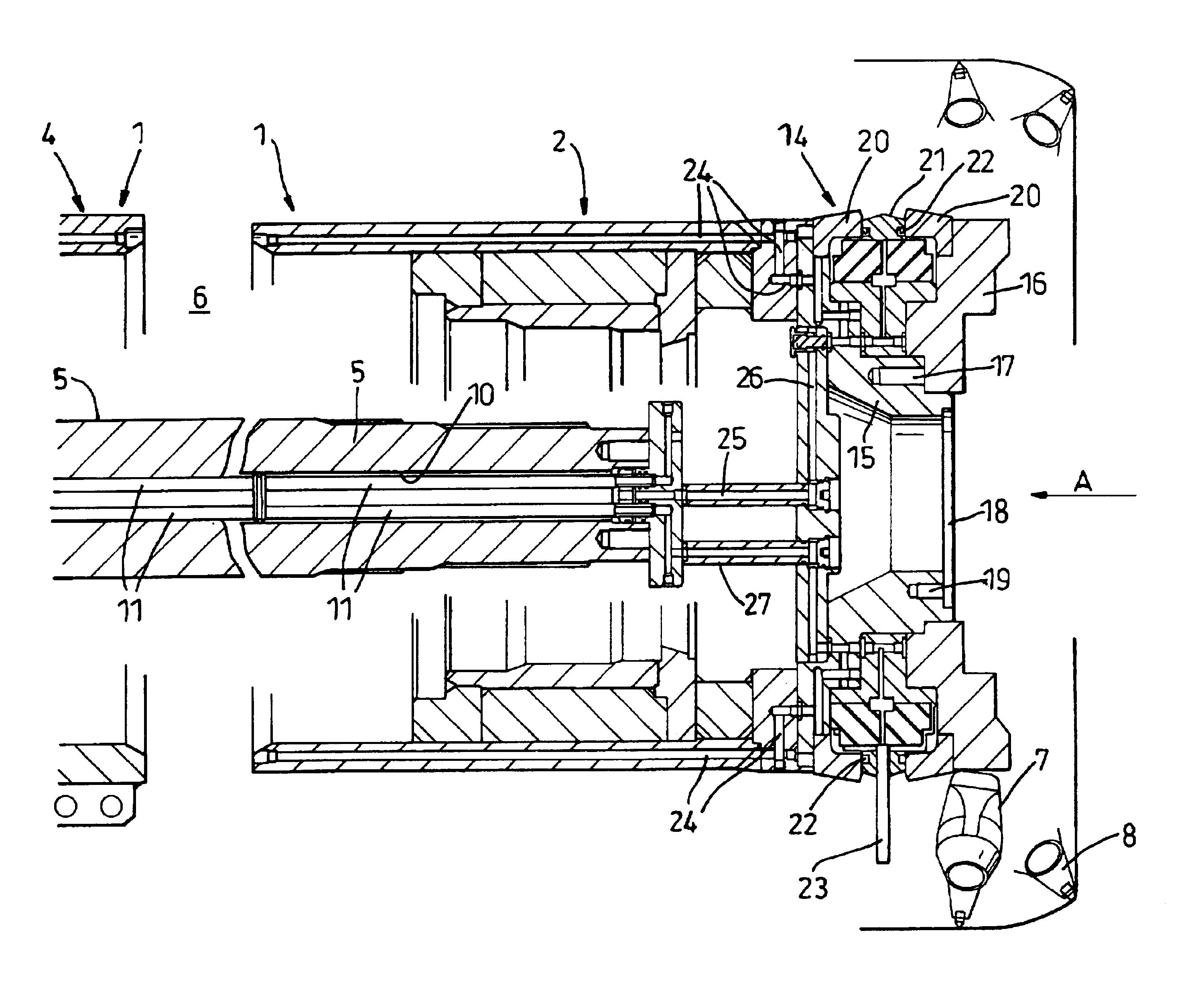
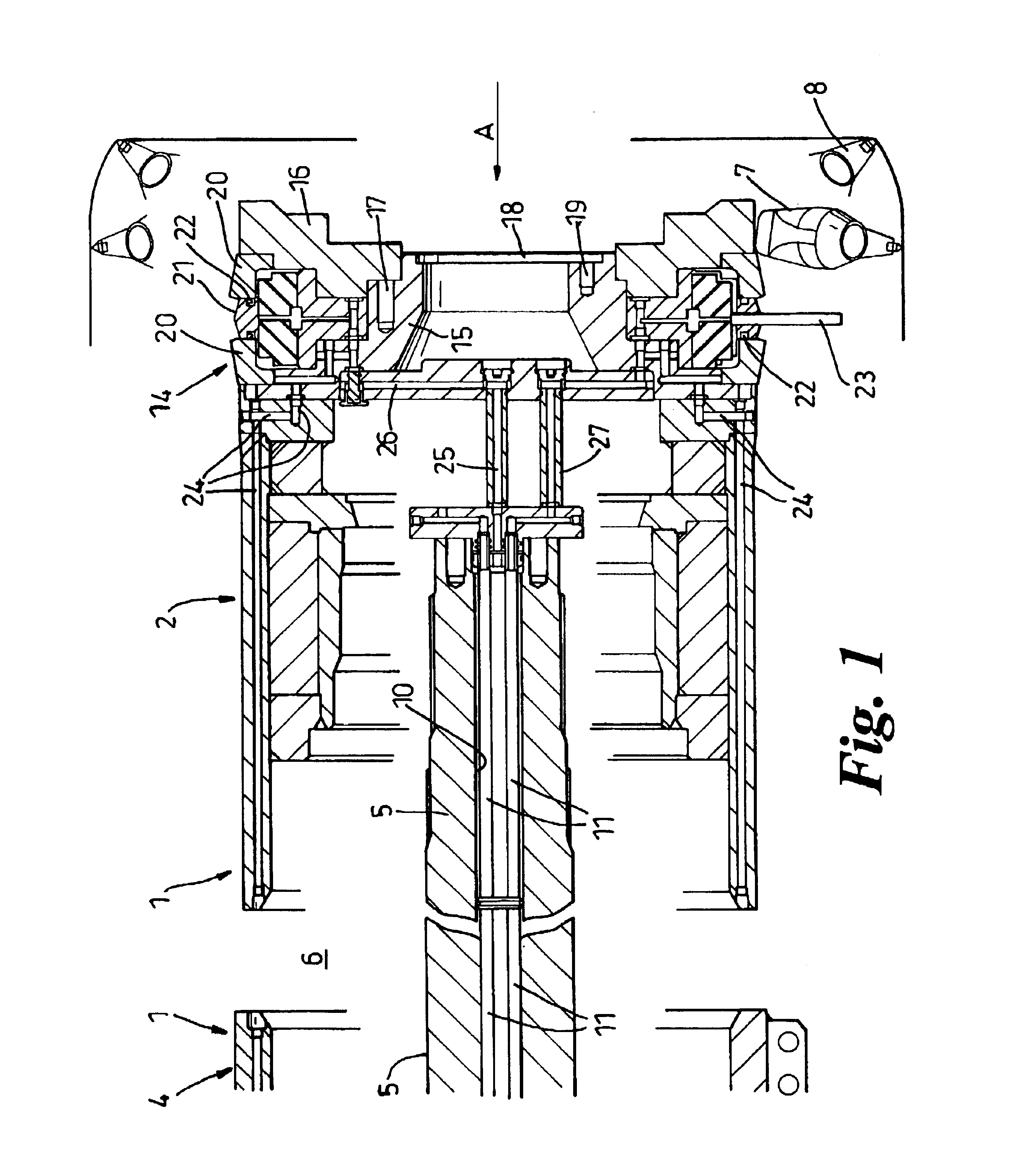
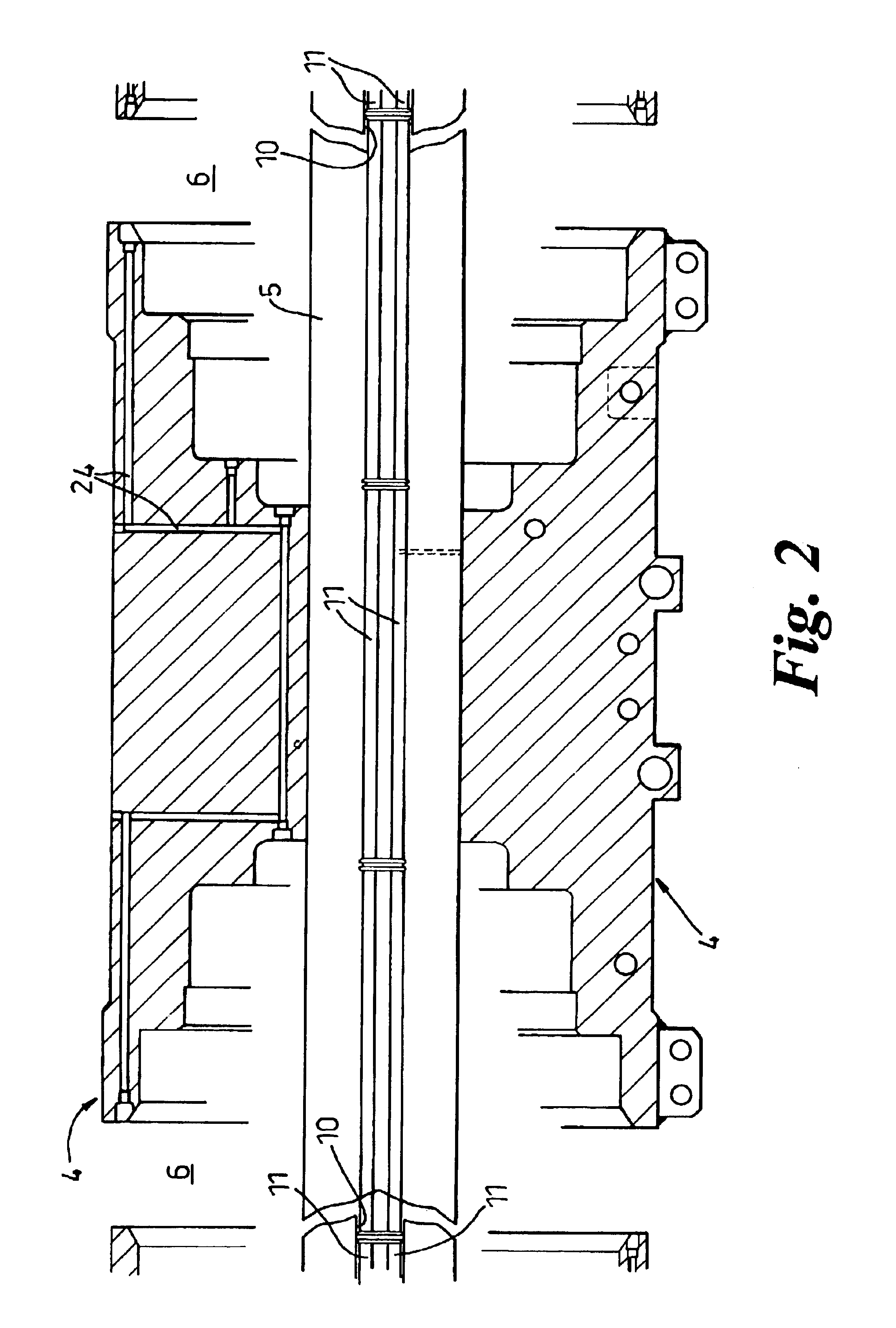
The rotary cutting head 1 in accordance with the invention comprises three co-axial drums, being a right hand outer drum 2, a left hand outer drum 3, and a central drum 4, the drums 2, 3 and 4 being secured on a common drive shaft 5, which is supported, in the well-known manner, from a pair of spaced-apart support arms projecting forwardly from a so-called continuous mining machine, the support arms housing a power drive train to the drive shaft 5, and being pivotally attached to the machine under the control of hydraulic rams to raise or lower the head 1, as dictated by mining requirements. The support arms penetrate the gaps 6 between each end of the central drum 4, and the adjacent ends of the left hand, and right hand, drums 3,2. For clarity, only FIGS. 1, 3 and 4 indicate pick boxes 7 that are welded at selected locations in a helical array around the drums 2, 3 and 4, each pick box being provided with a replaceable pick 8.

For a variety of well known reasons, water sprays are r...


PUM


Abstract

A rotary cutting head (1) for a mineral mining machine, comprises a drive shaft (5) carrying a central drum (4), and beyond each end of the central drum (4), an outer drum (2,3), each drum being provided with an array of pick boxes (7) to receive an individual pick (8), wherein the drive shaft (5) has a longitudinal bore (10) housing at least one water conveying tube (11), which together with a network of bores (25) enable a single water admission cartridge interposed between an outer end of one of the drums (2), and an end face plate (16) of that drum (2) to supply water to all three drums (2, 3, 4).

Description

RELATED / PRIORITY APPLICATIONThis application claims priority with respect to British Application No. 0200880.3, filed Jan. 16, 2002.FIELD OF THE INVENTIONThis invention relates to a rotary cutting head for a mining or tunnelling machine, and to a machine provided with such a cutting head.BACKGROUND OF THE INVENTIONIn GB 2297989, is described a so-called continuous miner, in which the hitherto “dry” rotary cutting head, comprising a drive shaft carrying a centre drum and two, co-axial outer drums, is provided with a safe supply of pressurised water whereby, if and when a water leak occurs, there is no leakage eg into a gear box, but only to an exterior part of the cutting head, and hence onto the mine floor. It was envisaged in GB 2297989 that each of the three drums would have its own individual water feed by a cartridge unit. This system has been used in practice and has had some degree of success. Inevitably, rotary water seals wear requiring the dismantling or changing of the car...

Claims


Application Information

Patent Timeline
IPC IPC(8): E21C25/00E21C25/10E21C35/00E21C35/23
CPCE21C35/23E21C25/10
Inventor CLAPHAM, WILLIAM STEPHENWARREN, JOHN JOSEPH
Owner ESCO HYDRA UK
Learn More