Aircraft seat with synchronized back rest and leg rest

Inactive Publication Date: 2005-08-16
ZODIAC SEATS FRANCE
View PDF16 Cites 38 Cited by
  • Summary
  • Abstract
  • Description
  • Claims
  • Application Information

AI Technical Summary

Benefits of technology

[0007]The invention also makes it possible to achieve this synchronisation whilst limiting the number of actuators necessary for obtaining the movements.
[0022]This arrangement makes it possible to keep the vertical position of the leg rest whatever the inclination of the squab, when the back rest is in the vertical position.
[0024]The connection between the connecting rod and the back rest is thus situated substantially level with the squab when the latter is horizontal, and below the squab when it is inclined. This arrangement avoids the connecting rod being interfered with by the squab.
[0026]Thus this ram damps the load borne by the various parts when a high load is exerted on the leg rest (for example by the passenger.
[0035]Thus this actuator controls both the inclination of the back rest and that of the leg rest, avoiding the presence of an actuator for the leg rest.

Problems solved by technology

This has a certain number of drawbacks; in particular this synchronisation cannot be achieved for a seat whose elements are independent of the fixed shell or for a seat which does not comprise a fixed shell.

Method used


Image

  • Aircraft seat with synchronized back rest and leg rest
  • Aircraft seat with synchronized back rest and leg rest
  • Aircraft seat with synchronized back rest and leg rest

Examples


Embodiment Construction

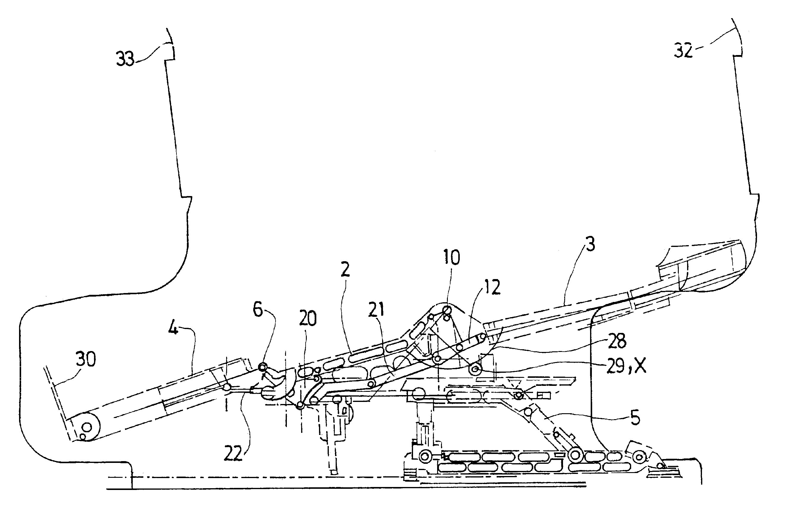
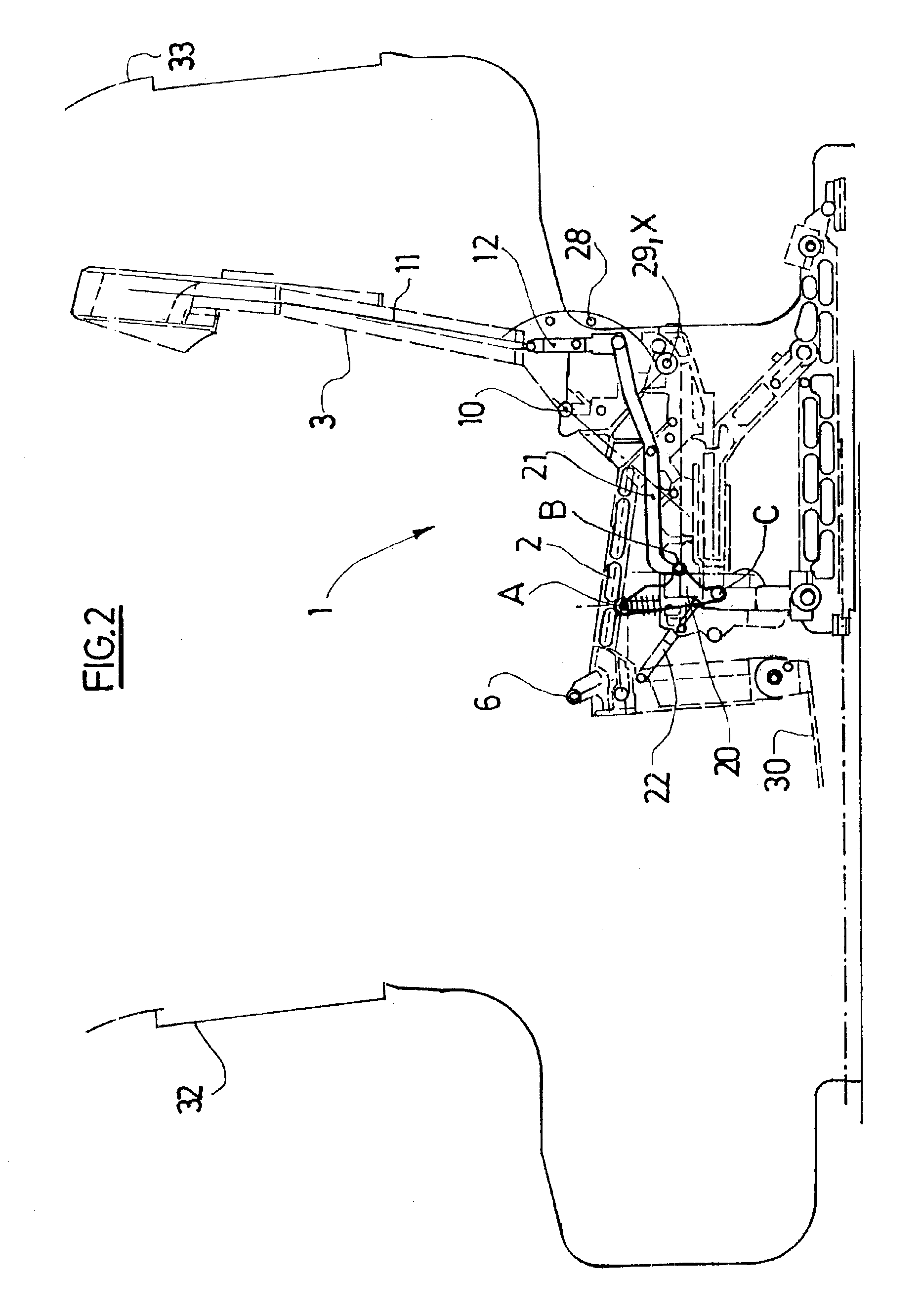
[0045]The seat 1 comprises a squab structure 2, a back rest structure 3, a leg rest structure 4 and a support structure 5 for the squab structure 2 and the back rest structure 3.

[0046]One end of the leg rest 4 is connected by a pivot connection 6 to the front end 2a of the squab structure 2.

[0047]The other end of the squab structure 2 is mounted so as to pivot with respect to the back rest structure 3 about a shaft 7. This shaft 7 is disposed on the bottom part of the back rest structure 3.

[0048]The squab structure 2 is also able to move in translation with respect to the support structure 5 in the longitudinal direction of the seat.

[0049]The support structure 5 comprises two parts: a fixed bottom part 5b secured to the floor of the aircraft and a top part 5a supporting the squab structure 2.

[0050]The top part 5a is able to move in translation with respect to the fixed bottom part 5b. This runner connection is for example achieved by means of a system of runners or a rack system, co...


PUM


Abstract

A seat (1) for a vehicle such as an aircraft, comprises a back rest structure (3) and a squab structure (2) mounted so as to pivot with respect to the back rest structure (3), a structure (5) supporting the squab structure (2) and the back rest structure (3), the back rest structure (3) being connected to the support structure (5) by a pivot connection (10), and a leg rest (4) connected by a pivot connection (6) to the front end of the squab structure (2), characterised in that it comprises mechanical synchronisation mechanism (15) able to synchronise the movements of the back rest structure (3) and of the leg rest (4). The mechanical synchronisation mechanism (15) is connected:to the back rest structure (3) by a pivot connection (23) situated at a distance from the pivot connection (10) between the back rest structure (3) and the support structure (5), between the pivot connection (10) and the bottom end (12) of the back rest structure,to the leg rest (4) by a pivot connection (24) situated close to the pivot connection (6) between the leg rest and the squab structure, at a certain distance from the latter, andto the squab structure (2) by a pivot connection (A) situated close to the pivot connection (6) between the leg rest and the squab structure, at a certain distance from the latter.

Description

BACKGROUND OF THE INVENTION[0001]The invention relates to a seat for an aircraft where the movements of the back rest and leg rest are connected and synchronised.[0002]The document EP-1 044 878 describes a seat comprising a back rest adjustable for inclination, a squab adjustable for inclination, a leg rest adjustable for inclination and a fixed rear separation shell disposed behind the seat back rest, one end of the leg rest being pivotally mounted at the front end of the squab. The side walls of the fixed separation shell comprise runners in which pinions fixed to the back rest can move along with the inclination of the back rest. The movement of the leg rest with respect to the squab is controlled by a programmed processor according to the location of the pinions in the runners. The device controlling the movement of the leg rest is disposed between the squab and the leg rest.SUMMARY AND OBJECTS OF THE INVENTION[0003]However, in this document, the movements of the leg rest and ba...

Claims


Application Information

Patent Timeline
IPC IPC(8): B60N2/34B60N2/22B60N2/44B60N2/32B64D11/06B64D11/00B60N2/20A47C1/035B60N2/90B64D25/04
CPCB60N2/22B60N2/34B64D11/064B64D11/06B60N2/4495B64D11/06395B64D11/0641B64D11/0643B60N2/995B64D11/0606
Inventor LAURENT, LIGONNIERE
Owner ZODIAC SEATS FRANCE
Why Eureka
Try Eureka