Sunshade with an illuminating device

a technology of sunshade and illuminating device, which is applied in the direction of lighting support devices, gymnastics, and power devices with built-in, etc., can solve the problems of troublesome use of generators and inability to find external power sources everywher

Inactive Publication Date: 2005-01-11
TUNG BENSON
View PDF3 Cites 48 Cited by
  • Summary
  • Abstract
  • Description
  • Claims
  • Application Information

AI Technical Summary

Benefits of technology

A sunshade in accordance with the present invention includes a post having a rib-mounting member mounted thereon, a plurality of ribs each having an upper end pivotally connected to the rib-mounting member, a runner slidably mounted on the post, a plurality of stretchers each having an upper end pivotally connected to an intermediate portion of an associated rib and a lower end pivotally connected to the runner, a solar energy device mounted on the sunshade for receiving solar energy and transforming solar energy into electricity, and at least one light unit mounted on at least one of the ribs. The light unit is electrically connected to the solar energy device, thereby providing illumination without the need of an external power source.

Problems solved by technology

However, use of the generator is troublesome.
Further, the external power source is not available everywhere.

Method used


Image

  • Sunshade with an illuminating device
  • Sunshade with an illuminating device
  • Sunshade with an illuminating device

Examples


second embodiment

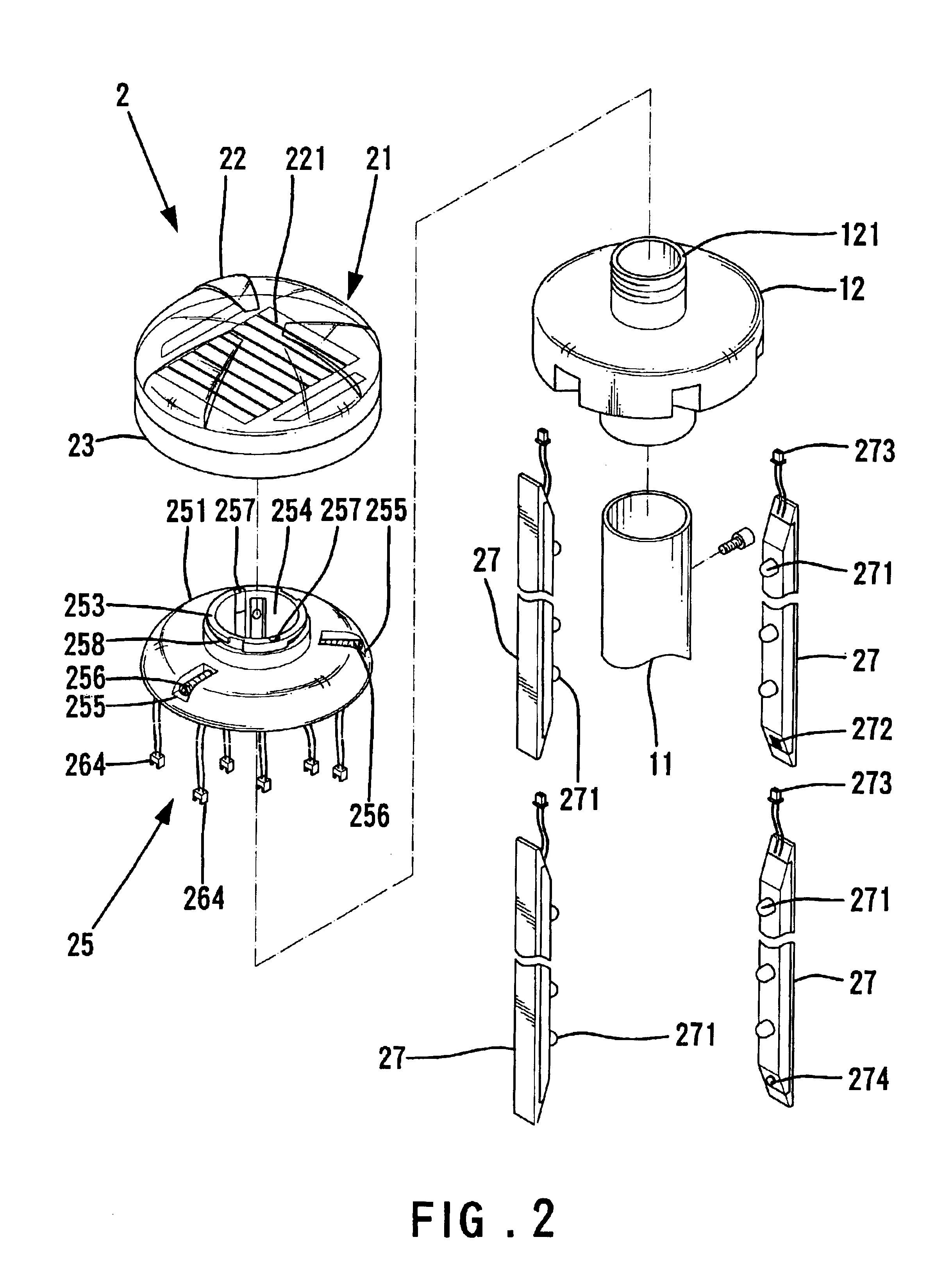
FIGS. 9 and 10 show the invention. In this embodiment, the illuminating device 2 is mounted to a wooden sunshade 3 that has a structure substantially the same as that shown in FIGS. 1 through 8. Specifically the, sunshade 3 includes a post 31, a rib-mounting member 32 on top of the post 31 and a plurality of ribs 33 each having an end pivotally connected to the rib-mounting member 32. What is characteristically different from the sunshade of FIGS. 1 through 8 is that the rib-mounting member (now designated by 32) of the sunshade 3 includes a through-hole 321, and the illuminating device 2 includes a corresponding connecting member 28 so as to be mounted on the rib-mounting member 32. The connecting member 28 includes an upper cover 281 and a base 282 mounted below the upper cover 281. A conductive post 283 is provided on top of the upper cover 281, and two conductive plates 284 are provided on the base 282, with the conductive plates 284 being electrically connected via wires 285 to...

third embodiment

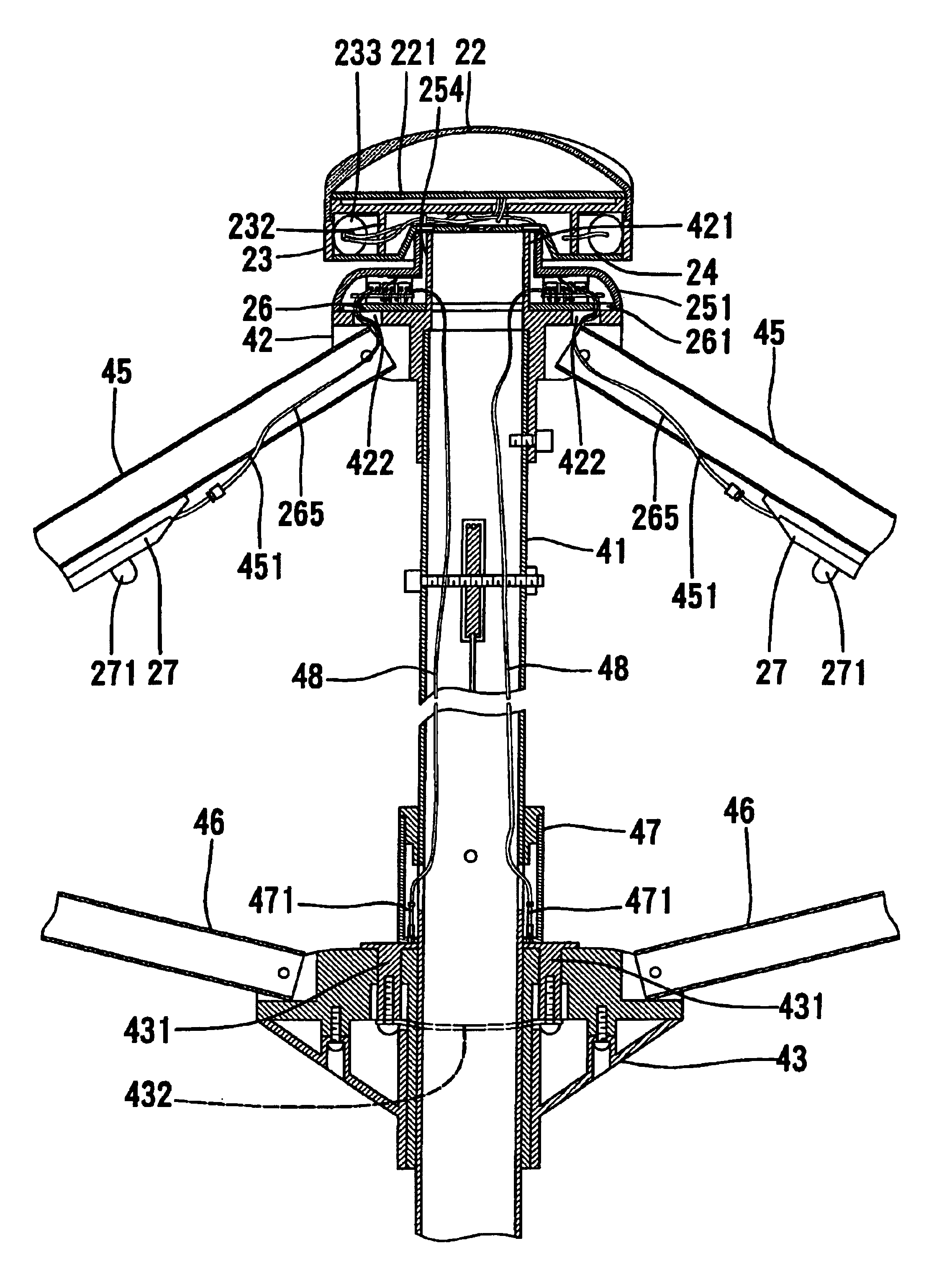
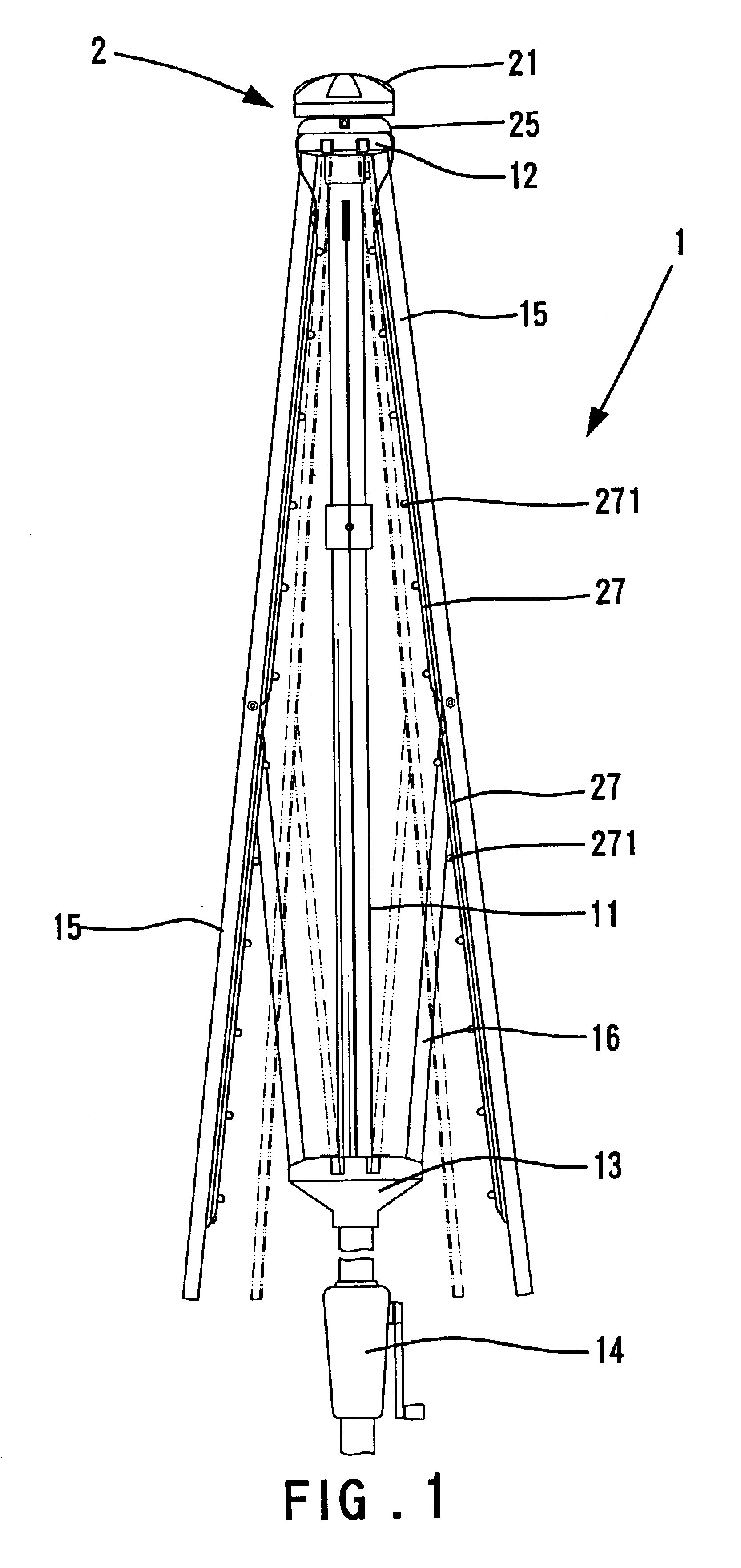
FIG. 11 shows the invention. The sunshade 4 comprises a post 41, a rib-mounting member 42 on top of the post 41, a plurality of ribs 45 each having an end pivotally connected to the rib-mounting member 42, a runner 43 slidably mounted to the post 41, a plurality of stretchers 46 each having a first end pivotally connected to the runner 43 and a second end pivotally connected to an intermediate portion of an associated one of the ribs 45. A reel 44 is provided to the post 41 for unfolding and folding the sunshade 4. A tubular member 421 is provided on top of the rib-mounting member 42. Further, the rib-mounting member 42 has a plurality of through-holes 422. Each rib 45 has a transverse hole 451 in an upper end thereof. A positioning sleeve 47 is fixed to the post 41 of the sunshade 4 and located above the runner 43. Two conductive pins 471 are provided in the positioning sleeve 47, and the runner 43 includes two conductive pegs 431 that are extended into the runner 43 and electrical...


PUM


Abstract

A sunshade includes a post having a rib-mounting member mounted thereon, a plurality of ribs each having an upper end pivotally connected to the rib-mounting member, a runner slidably mounted on the post, a plurality of stretchers each having an upper end pivotally connected to an intermediate portion of an associated rib and a lower end pivotally connected to the runner, a solar energy device mounted on the sunshade for receiving solar energy and transforming solar energy into electricity, and at least one light unit mounted on at least one of the ribs. The light unit is electrically connected to the solar energy device, thereby providing illumination without the need of an external power source.

Description

BACKGROUND OF THE INVENTION1. Field of the InventionThe present invention relates to a sunshade with an illuminating device for providing outdoor illumination.2. Description of the Related ArtA sunshade shields people from sunlight and is thus widely used in outdoor cafes and rest areas as well as on beaches. An illuminating device is attached to a sunshade for illumination purposes, and an external power source is required. Typically, one or more bulbs are attached to the sunshade and connected to an indoor socket or a generator. However, use of the generator is troublesome. Further, the external power source is not available everywhere. The present invention is intended to provide a sunshade with an illuminating device to meet this end.SUMMARY OF THE INVENTIONAn object of the present invention is to provide a sunshade with an illuminating device that has a solar energy receiver for receiving solar energy and providing electricity to the bulbs attached to the sunshade.A sunshade in...

Claims


Application Information

Patent Timeline
Patent Type & Authority Patents(United States)
IPC IPC(8): A45B3/04A45B3/00F21V33/00F21S9/00F21S9/03
CPCA45B3/04F21V33/006F21S9/035A45B2200/1027Y10S135/91
Inventor TUNG, BENSON
Owner TUNG BENSON
Why Eureka
Try Eureka