Resistive suction muffler for refrigerant compressors

a compressor and suction tube technology, applied in the direction of positive displacement liquid engines, piston pumps, domestic cooling apparatus, etc., can solve the problem of lowering the overall level of sound transmitted, and achieve the effect of lowering the overall level of sound

Inactive Publication Date: 2005-01-11
BRISTOL COMPRESSORS INT
View PDF33 Cites 22 Cited by
  • Summary
  • Abstract
  • Description
  • Claims
  • Application Information

AI Technical Summary

Benefits of technology

The present invention is a compressor with a resistive muffler that can reduce sound levels across a wide range of frequencies. This muffler uses an acoustic foam that is resistant to deterioration in the harsh environment of the compressor. Additionally, the muffler will continue to function even when the foam is saturated with lubricant or refrigerant. This invention has the advantage of reducing noise transmitted to the environment, and improving the overall performance of the compressor.

Problems solved by technology

The technical problem addressed in this patent text is the need for a resistive muffler that can effectively absorb sound over a broad range of frequencies in the harsh environment of a refrigerant compressor. The current methods used to control or attenuate compressor noise have limitations, and there is a need for a muffler that can withstand the high temperatures, pressures, and chemical exposures of the compressor. The patent text describes the common sources of noise in compressors and the various methods that have been attempted to reduce or attenuate the noise.

Method used


Image

  • Resistive suction muffler for refrigerant compressors
  • Resistive suction muffler for refrigerant compressors
  • Resistive suction muffler for refrigerant compressors

Examples


second embodiment

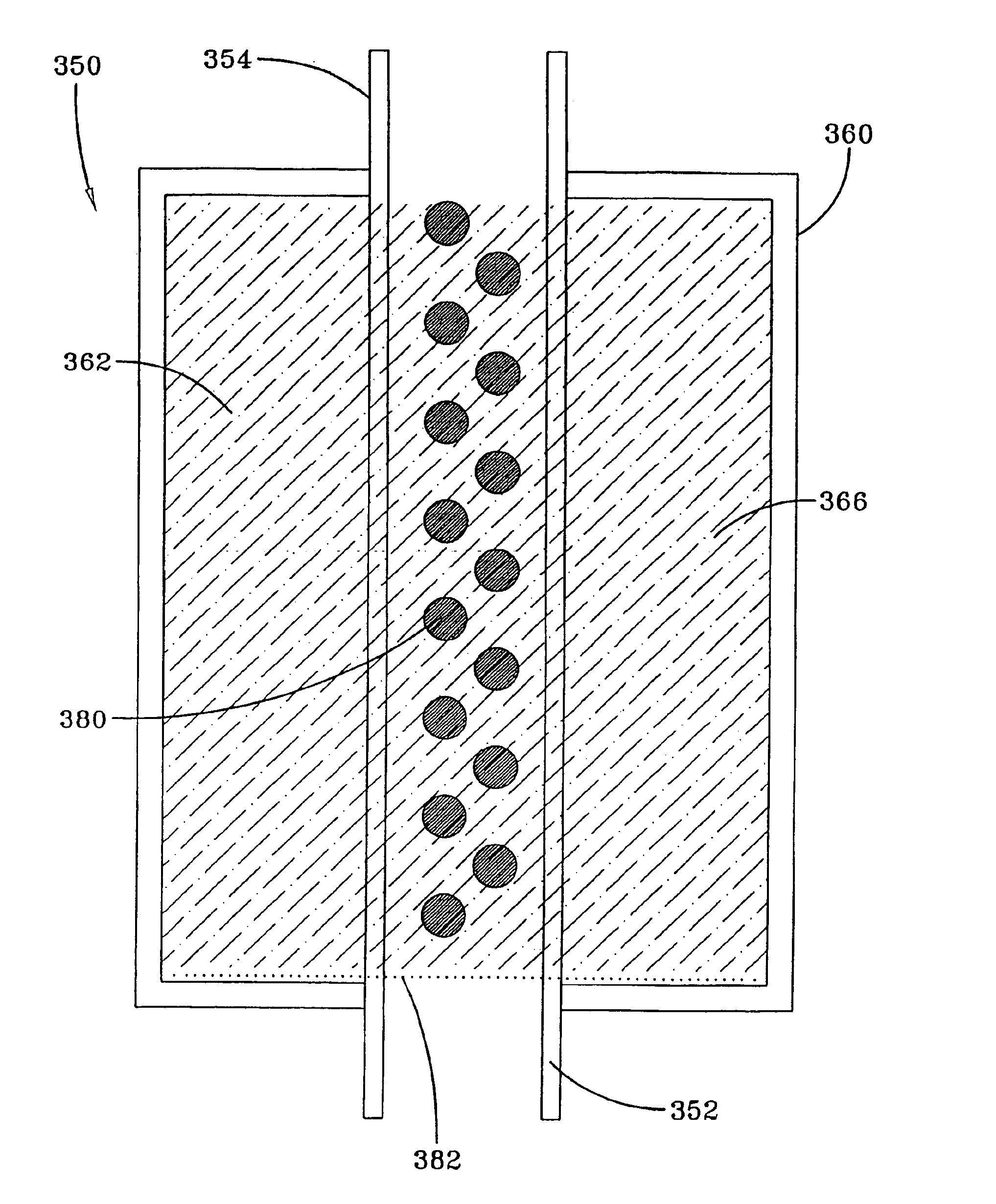
the present invention is shown in cross section in FIG. 3. Here, resistive muffler 350 includes a muffler housing 360, an exhaust tube 352 exiting housing 360 on the piston assembly 30 side of muffler and an intake tube 354 entering housing 360 on the suction line 12 side of muffler 350. Housing forms a chamber 362 so that gas passes from intake tube 354 to exhaust tube 352. As shown in FIG. 3, intake tube 354 and exhaust tube 352 are contiguous, forming a single tube. This is not required, and intake tube 354 and exhaust tube 352 may be individual tubes connected together, separated by a short distance or separated by the length of the muffler. Housing 360 forms a chamber 362 that is filled with acoustic foam 366. However, in order to take full advantage of the attenuation capabilities of acoustic muffler 350, there must be a path or passageways available to allow gas passing through muffler 350 to contact acoustic foam. This path is provided by a plurality of apertures 380 in cont...


PUM


Abstract

A resistive muffler attenuates sound generated by the gas intake and suction valve during compressor operation of a refrigerant compressor. The resistive muffler is assembled inline with the suction gas flow of the compressor and is positioned within the compressor housing. The resistive muffler attenuates the sound generated by the compressor during its operation as refrigerant gas is drawn into the compressor from an evaporator and passes through the resistive muffler in transit to the suction valve and hence to the region of the compressor where the gas is physically compressed. The resistive muffler includes a muffler housing having an intake end and an exhaust end. An acoustic foam assembly is incorporated into the muffler housing. The acoustic foam assembly is selected on the basis of its ability to absorb sound over a broad range of frequencies and is the muffler containing the acoustic foam is assembled within the compressor so that the sound does not bypass the muffler and transmit significant amounts of the sound to the compressor housing. The acoustic foam remains chemically inert when exposed to the compressor fluids at elevated temperatures of operation, and retains its ability to absorb sound over a broad range of frequencies even when saturated with compressor fluids. The foam assembly should also be able to withstand very large pressure fluctuations without experiencing deterioration.

Description


Claims


Application Information

Patent Timeline
Owner BRISTOL COMPRESSORS INT
Why Eureka
Try Eureka