System of contra-rotating propellers driven by a planetary gear train providing a balanced distribution of torque between the two propellers

a technology of contra-rotating propellers and gear trains, which is applied in the field of system of contra-rotating propellers, can solve the problems of increasing the overall mass of the propeller system, adversely affecting the turbomachine, limiting the propulsion efficiency, and increasing deleteriously the acoustic level of the turbomachine, so as to prevent the deleterious appearance of residual gyration of the output flow, reduce the acoustic level, and improve the propulsion efficiency

Active Publication Date: 2014-11-04
SN DETUDE & DE CONSTR DE MOTEURS DAVIATION S N E C M A
View PDF15 Cites 23 Cited by
  • Summary
  • Abstract
  • Description
  • Claims
  • Application Information

AI Technical Summary

Benefits of technology

[0017]This feature leads to a balance of the two torques transmitted respectively to the two propellers, and the ratio between these two torques is effectively equality. The consequence is, firstly, that both propellers will each generate a roughly identical gyration of the secondary flow, which prevents the deleterious appearance of a residual gyration of the output flow. Thus, the aerodynamic flow is satisfactorily rectified at the output from the propeller system, which procures an improved propulsion efficiency and a reduction of the acoustic level produced.
[0018]Furthermore, as a consequence of this balancing of the torques, the means used for mounting the turbomachine on the aircraft are subject to less mechanical stress, and can consequently be of a less costly design in terms of encumbrance and mass.
[0019]Moreover, within the contra-rotating free power turbine, the first rotor can rotate less rapidly than in the case of a traditional turbine, whilst preserving the same power delivered at the output of this turbine. This reduction of the rotational speed of the first rotor not only allows its design to be facilitated and simplified, since the centrifugal forces applied to it are lesser, but also enables the reduction ratio conferred by the planetary gear train to be reduced, since the speed of its sun gear, driven by the first rotor, is lower. A substantial gain in terms of mass obviously results from these two advantages.
[0020]Moreover, it should be noted that a reduction gear is characterised by mechanical efficiency, implying that a part of the transmitted power is transformed into heat. Given the power of several megawatts supplied by the aircraft turbomachine, this heat is very substantial. These calories are habitually evacuated by means of an oil circuit, and an air-oil exchanger. The installation of this exchanger in the nacelle constitutes a major constraint for the integration of the propulsive assembly, due to its encumbrance, mass and drag. With the planetary gear train implemented according to the invention, part of the power no longer transits through the reduction gear, but is transmitted directly to the second propeller. Consequently, the quantity of calories to be dissipated in the exchanger is lesser, such that the latter can be of smaller dimensions. This therefore has a beneficial effect for the mass, encumbrance and drag of the air-oil exchanger.

Problems solved by technology

In addition, the increase of the reduction ratio R inevitably leads to an increase of the overall mass of the propeller system, having an adverse effect on the turbomachine.
As a consequence of the unequal ratio between the torques, one of the two propellers will generate a greater gyration of the secondary flow than the other propeller, causing a residual gyration of the output flow, appreciably limiting the propulsion efficiency and increasing deleteriously the acoustic level of the turbomachine.
Moreover, this difference between the two torques also generates an increased stress of the means used for mounting the turbomachine on the aircraft, and these means must accordingly be over-dimensioned to support the extra load which is applied to them.

Method used


Image

  • System of contra-rotating propellers driven by a planetary gear train providing a balanced distribution of torque between the two propellers
  • System of contra-rotating propellers driven by a planetary gear train providing a balanced distribution of torque between the two propellers
  • System of contra-rotating propellers driven by a planetary gear train providing a balanced distribution of torque between the two propellers

Examples


Embodiment Construction

[0028]This description will be made with reference to the attached illustrations, among which

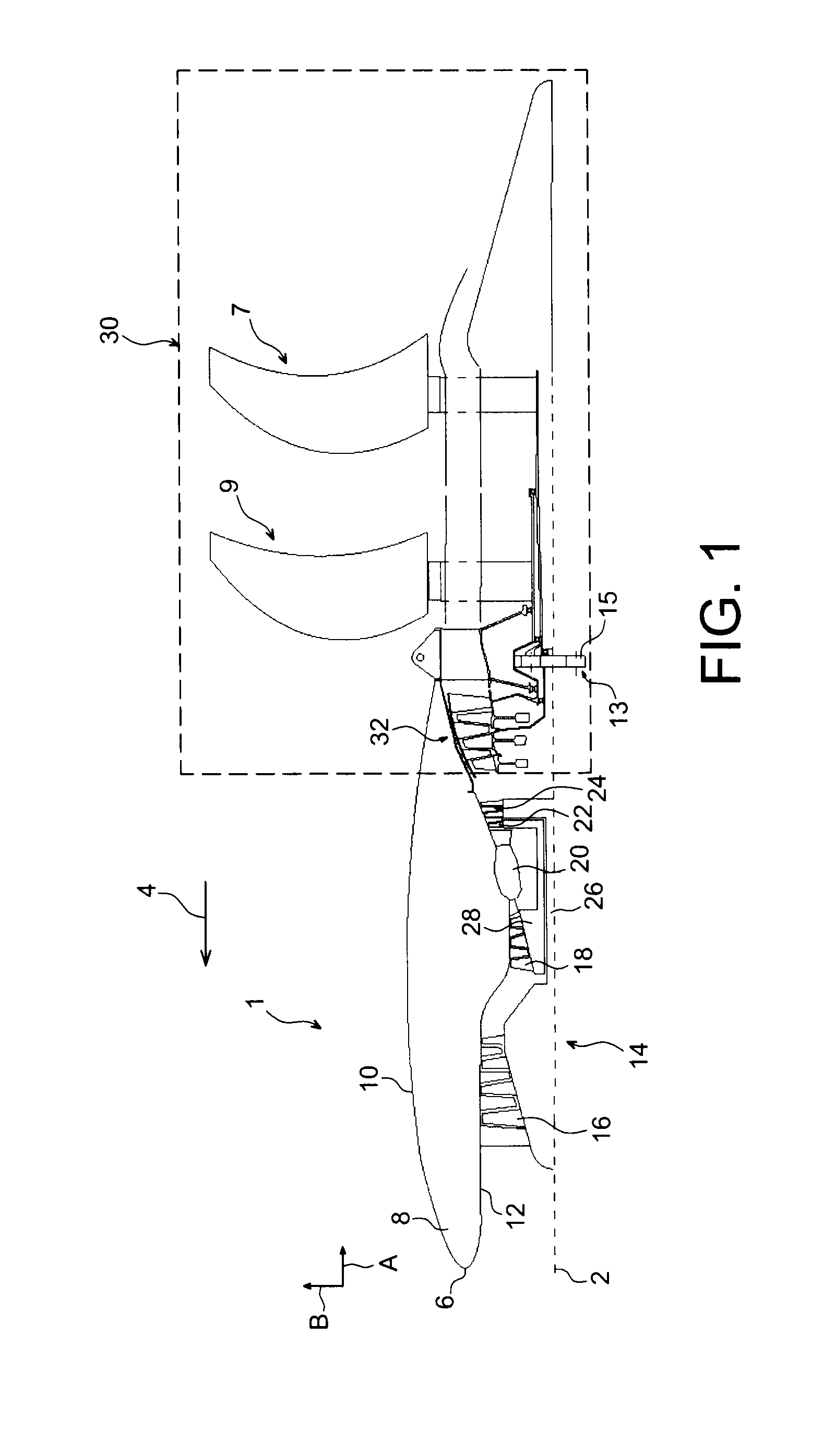
[0029]FIG. 1 represents a schematic lengthways half-section view of a turbomachine for aircraft, according to a preferred embodiment of the present invention;

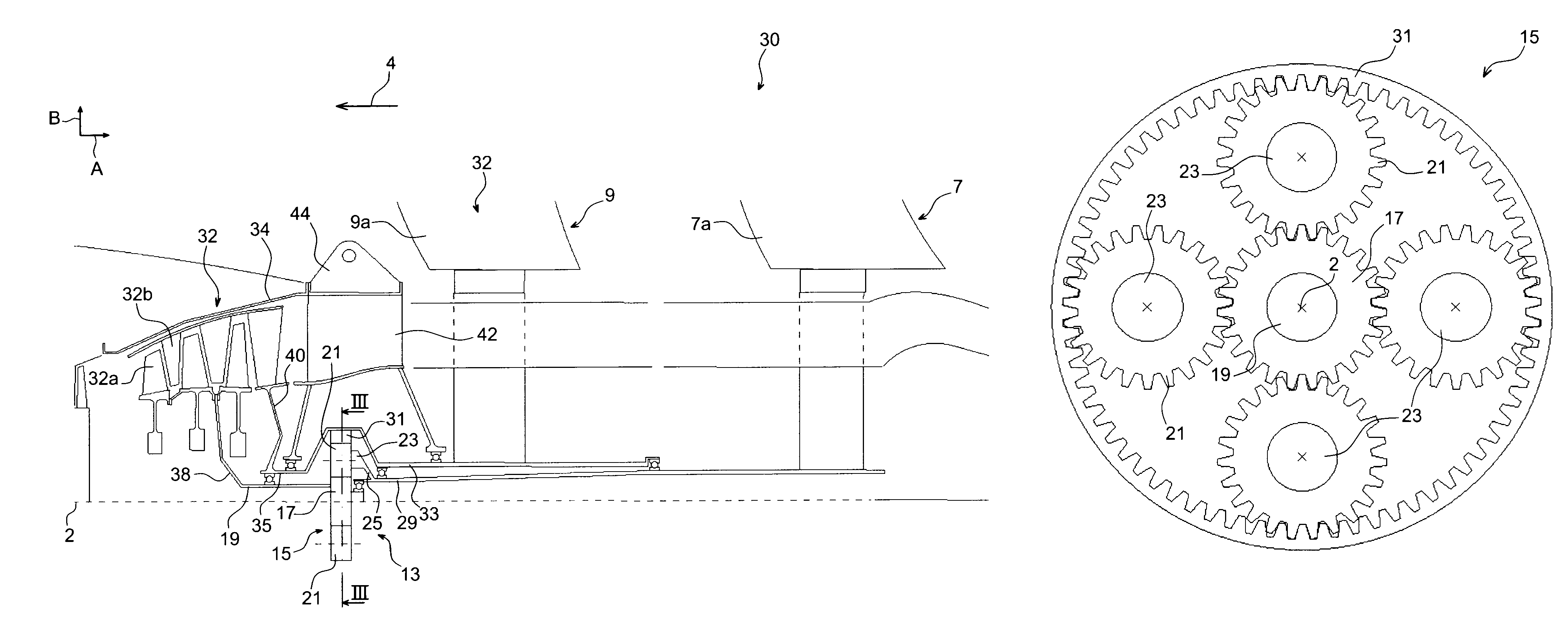
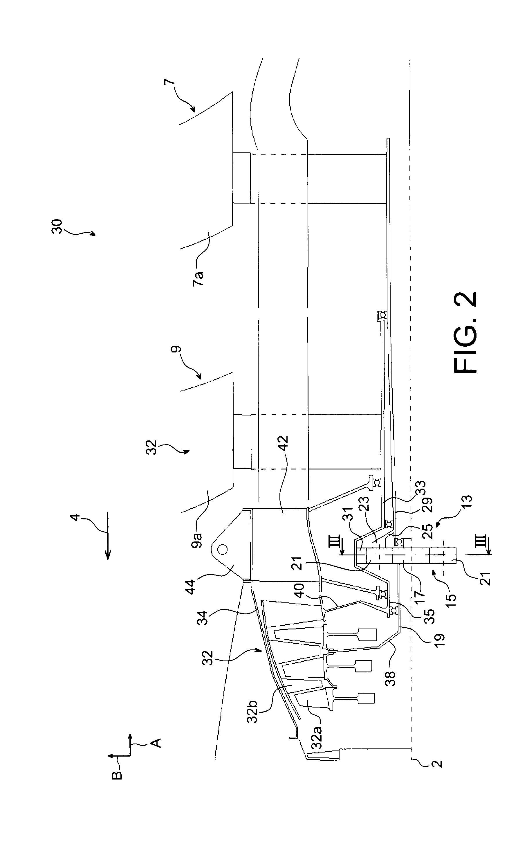
[0030]FIG. 2 represents an enlarged view of the system of contra-rotating propellers fitted to the turbomachine shown in FIG. 1; and

[0031]FIG. 3 represents a section view taken along line III-III of FIG. 2.

DETAILED ACCOUNT OF PREFERRED EMBODIMENTS

[0032]With reference to FIG. 1, a turbomachine 1 of the “open rotor” type according to a preferred embodiment of the present invention can be seen.

[0033]In the figures, direction A is the lengthways direction or axial direction, parallel to lengthways axis 2 of the turbomachine. Direction B, for its part, is the radial direction of the turbomachine. In addition, arrow 4 shows the direction of motion of the aircraft under the action of the thrust of turbomachine 1, where this motion direction is...


PUM


Abstract

A system of contra-rotating propellers for an aircraft turbomachine, including: a free power turbine including a first rotor; first and second propellers; and a mechanical transmission system including a planetary gear train fitted with a sun gear driven by the rotor, at least one planet gear driving the first propeller, and a ring driving the second propeller. The free power turbine also includes a second rotor that is contra-rotating relative to the first rotor, and rotating the ring.

Description

TECHNICAL FIELD[0001]The present invention relates, generally, to a system of contra-rotating propellers, for an aircraft turbomachine.[0002]The invention also concerns a turbomachine for aircraft including such a system of contra-rotating propellers.[0003]The invention preferably applies to aircraft turbomachines, for example of the jet turbine or turboprop engine type. It applies more particularly to turbomachines called “open rotor” turbomachines, within which a free power turbine drives both contra-rotating propellers, directly or indirectly through a mechanical transmission system forming a reduction gear and notably including a planetary gear train. In these systems of contra-rotating propellers, the propellers therefore have no fairing at their outer radial ends.STATE OF THE PRIOR ART[0004]From the prior art, turbomachines with systems of contra-rotating propellers are indeed known, the propellers of which are driven by a mechanical transmission system, habitually taking the ...

Claims


Application Information

Patent Timeline
Patent Type & Authority Patents(United States)
IPC IPC(8): F02C7/36B64C11/48F02C3/067F02K3/072F01D1/26
CPCF02K3/072Y02T50/671Y02T50/66F02C3/067B64C11/48F05D2260/96F02C7/36F05D2260/40311Y02T50/60
Inventor BALK, WOUTERCHARIER, GILLES ALAINGALLET, FRANCOIS
Owner SN DETUDE & DE CONSTR DE MOTEURS DAVIATION S N E C M A
Why Eureka
Try Eureka