Muffler unit for general-purpose engine

a general-purpose engine and muffler technology, applied in the direction of engines, mechanical equipment, machines/engines, etc., can solve the problems of low efficiency of muffler mounting operation using such small space, unpleasant oscillation noise, undue oscillation, etc., to achieve smooth placement or set in an operating position, the effect of increasing efficiency

Active Publication Date: 2009-02-12
HONDA MOTOR CO LTD
View PDF25 Cites 23 Cited by
  • Summary
  • Abstract
  • Description
  • Claims
  • Application Information

AI Technical Summary

Benefits of technology

[0023]With this angled arrangement of the first and second stud bolts, a tool used for tightening a nut onto a corresponding one of the first stud bolts can be smoothly-placed or set in an operating position without interference with the nuts already tightened onto the second stud bolts.
[0024]Preferably, each of the second stud bolts is offset

Problems solved by technology

With this arrangement, since the muffler 333 is supported by the exhaust pipe 334 in a cantilevered fashion, the muffler 333 is likely to cause undue

Method used


Image

  • Muffler unit for general-purpose engine
  • Muffler unit for general-purpose engine
  • Muffler unit for general-purpose engine

Examples


Embodiment Construction

[0045]One preferred embodiment of the present invention will be described below in greater detail with reference to the accompanying sheets of drawings.

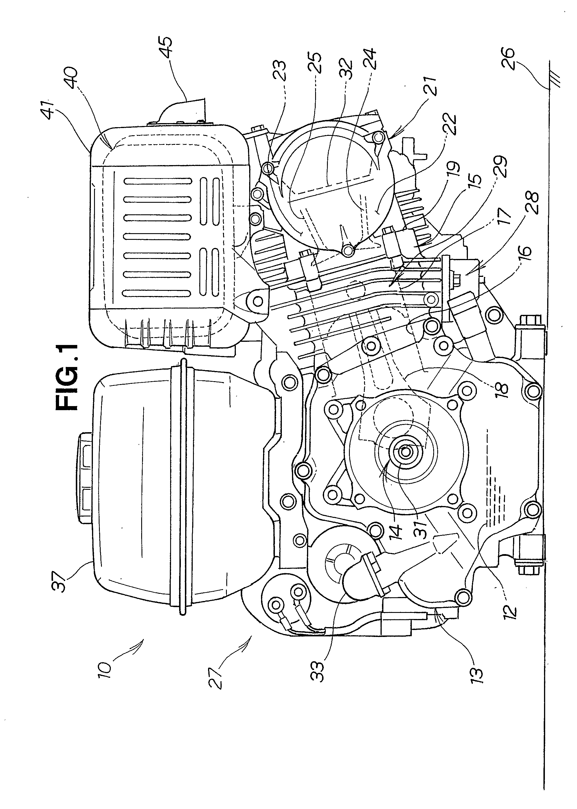
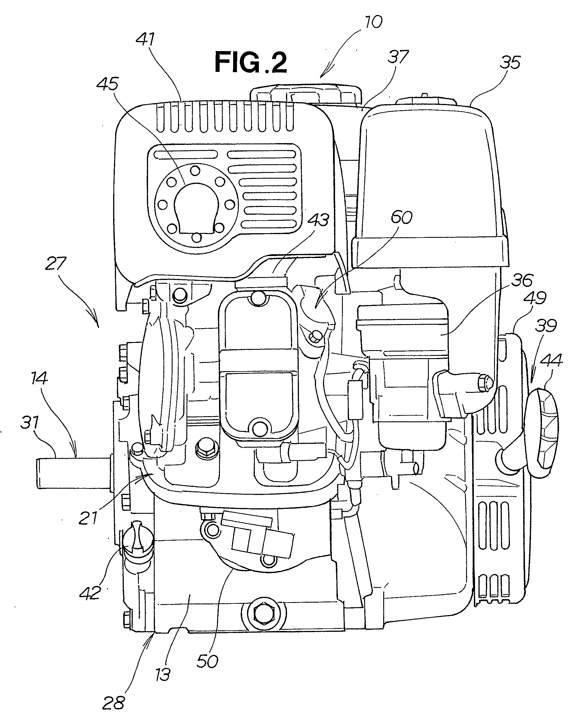
[0046]FIGS. 1 to 3 show a general-purpose engine 10 equipped with a muffler unit according to an embodiment of the present invention. The engine 10 generally comprises an engine body 27 and auxiliary devices associated with the engine body 27 for operation of the engine 10.

[0047]As shown in FIG. 1, the engine body 27 is of the so-called “air-cooled inclined single-cylinder overhead camshaft (OHC)” type and includes a crankcase 13 for holding therein a lubricating oil 12, a crankshaft (output shaft) 14 mounted horizontally and rotatably on the crankcase 13, a single cylinder block 15 formed in one piece with the crankcase 13 and inclined to the vertical, a reciprocating piston 17 slidably received in a cylinder 16 formed in the cylinder block 15, a connecting rod 18 forming a link between the piston 17 and the crankshaft 14, a cylinde...


PUM


Abstract

A muffler unit for a general-purpose engine includes a muffler (40) having a maze of sound-deadening chambers (101, 102, 103) defined therein and an inlet pipe (85) disposed inside the muffler. The inlet pipe has an open end (106) connected to an exhaust port of the engine via an exhaust pipe (43), a closed end (107) opposite to the open end, and perforations (108) provided near the open end and connecting an internal space of the inlet pipe and a first sound-deadening chamber (101). The closed end of the inlet pipe is exposed to the outside air, so that exhaust gasses are cooled when the gasses impinge on the closed end of the inlet pipe.

Description

TECHNICAL FIELD[0001]The present invention relates to a muffler unit for general-purpose engines, and more particularly to such a muffler unit including a muffler connected to an exhaust port of the engine via an exhaust pipe.BACKGROUND ART[0002]Muffler units used in general-purpose engines are known as disclosed, for example, in Japanese Utility Model Publication (JP-UM-A) No. 2-99214, Japanese Patent Publication (JP-A) No. 2003-097289, and Japanese Utility Model Publication (JP-UM-A) No. 59-194521.[0003]FIG. 17 hereof illustrates a muffler unit disclosed in JP-UM-A 2-99214. As shown in this figure, the disclosed muffler unit includes a muffler 300 having a pair of housing members 301 and 302 connected together with a partition wall 303 disposed therebetween. The muffler 300 has two sound-deadening chambers 304, 305 defined therein on opposite sides of the partition wall 303. The housing member 304 has an inlet opening 308 through which the first chamber 304 communicates with an ex...

Claims


Application Information

Patent Timeline
IPC IPC(8): F01N1/08F01N7/08F01N13/08F01N13/18
CPCF01N1/003F01N1/089F01N1/10F01N3/05F01N13/002Y02T10/20F01N13/1833F01N13/1855F01N2470/02F01N2470/04F01N2470/18F01N13/1805Y02T10/12F01N1/08F01N1/02F01N13/08
Inventor SATO, YOSHIKAZUSAKAMOTO, KAZUHIRONAOE, GAKUHONDA, SOUHEI
Owner HONDA MOTOR CO LTD
Why Eureka
Try Eureka