Vortex muffler

a technology of muffler and valve body, which is applied in the direction of machines/engines, gas passages, gas chambers, etc., can solve the problems of increasing the cost of oil, the difficulty of meeting federal mileage requirements, and the pollution level in metropolitan areas remains unacceptably high, so as to improve the flow, reduce the exhaust sound level, and improve the effect of flow

Active Publication Date: 2008-02-19
WALL ALAN
View PDF21 Cites 22 Cited by
  • Summary
  • Abstract
  • Description
  • Claims
  • Application Information

AI Technical Summary

Benefits of technology

[0007]The present invention addresses the above and other needs by providing a muffler which includes an inner passage residing in an outer shell, and a stationary fan residing in the inner passage. The fan creates a vortex in a flow through the inner passage thus improving the flow and reducing the exhaust sound level. The inner passage includes an inner passage shell and the fan comprises vanes extending inward from the inner passage shell and turned at approximately a 45 degree angle to a centerline of the inner passage. Pinch zones at the entrance and exit from the inner passage further reduce the exhaust sound level. The inner passage shell is preferably a perforated inner passage shell, and a sound deadening material resides between perforated inner passage shell and the outer shell.

Problems solved by technology

The increasing cost of oil has motivated car owners and manufacturers to seek means to improve vehicle mileage.
However, meeting federally mandated mileage requirements remains a challenge and further improvements are necessary.
Pollution levels in metropolitan areas remain unacceptably high at times, and create an immediate direct health issue for humans, and a longer term issue due to the damage to plant life.
Automotive-based pollution remains an issue, and auto makers are continually challenged to reduce the emissions from new automobiles.
But while the intake aspect of engine design has advanced drastically, exhaust systems have not similarly advanced.

Method used


Image

  • Vortex muffler
  • Vortex muffler
  • Vortex muffler

Examples


Embodiment Construction

[0019]The following description is of the best mode presently contemplated for carrying out the invention. This description is not to be taken in a limiting sense, but is made merely for the purpose of describing one or more preferred embodiments of the invention. The scope of the invention should be determined with reference to the claims.

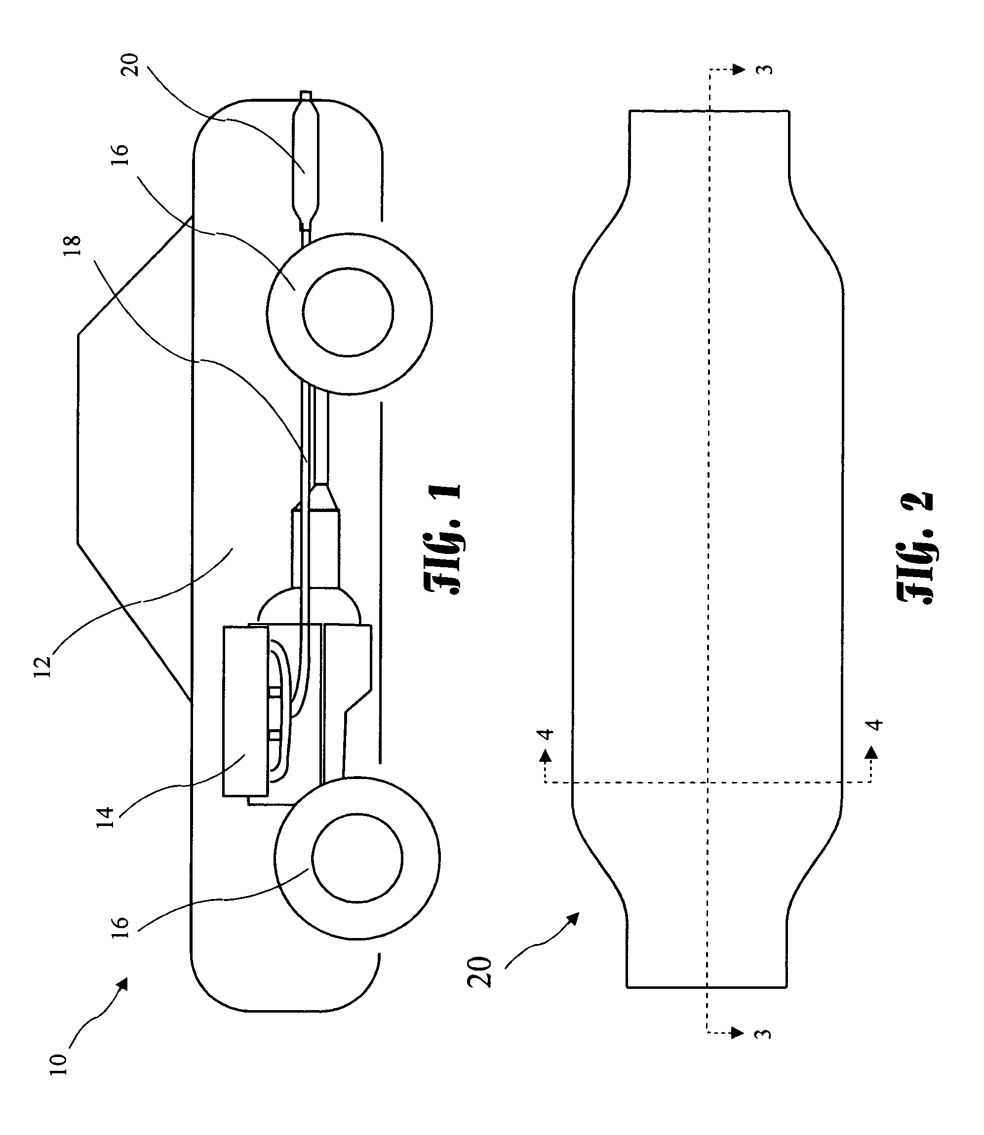
[0020]A vehicle 10 including a body 12, an engine 14, and wheels 16 is shown in FIG. 1. The engine 14 consumes fuel and produces exhaust which passes through an exhaust pipe 18 and exits the vehicle through a vortex muffler 20 according to the present invention. The muffler 20 may be used independently, or in conjunction (for example, in sequence or in parallel) with other exhaust devices such as a catalytic converter or another muffler. In vehicles with two or more exhaust pipes 18, one muffler 20 may be used with each exhaust pipe 18.

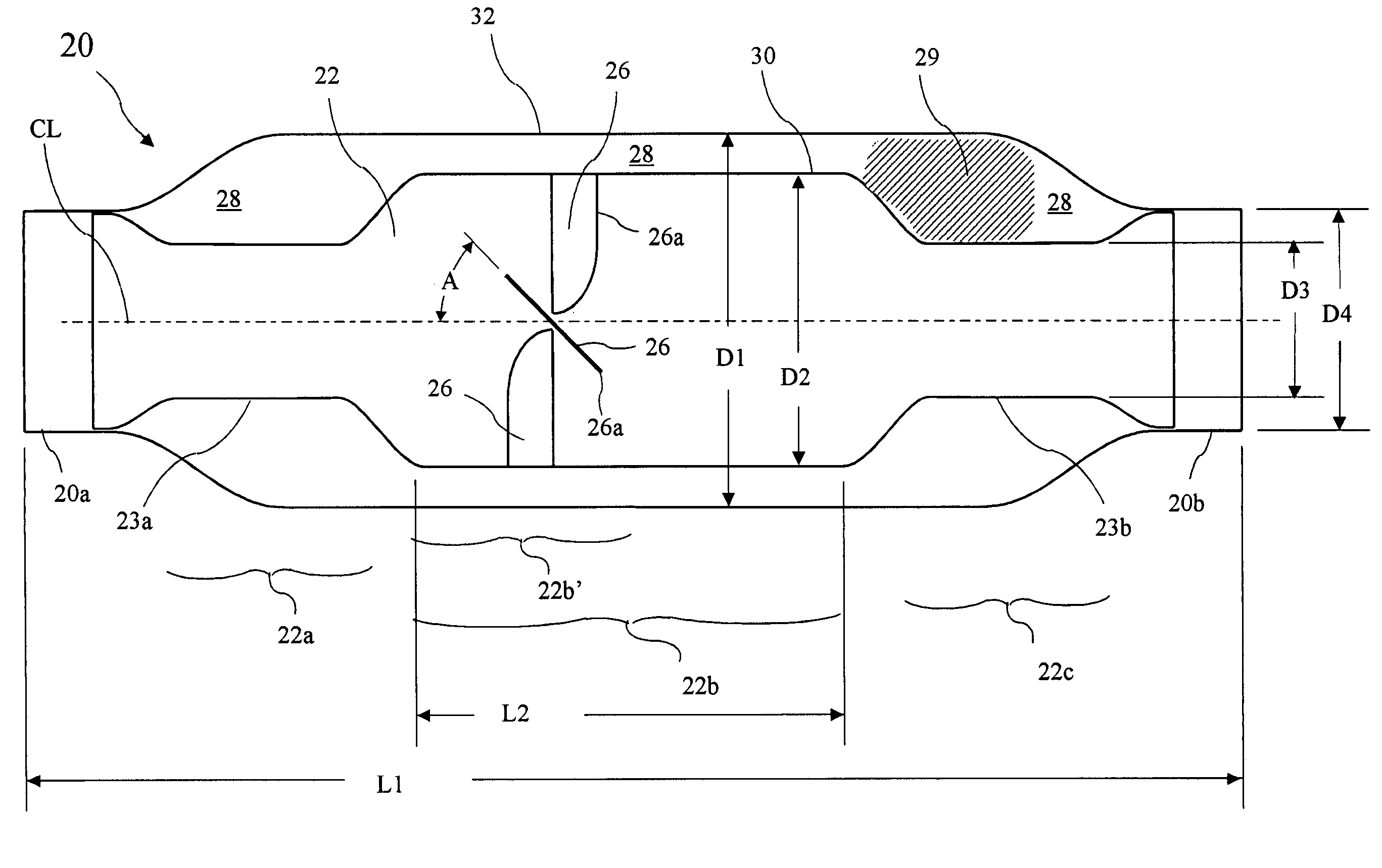
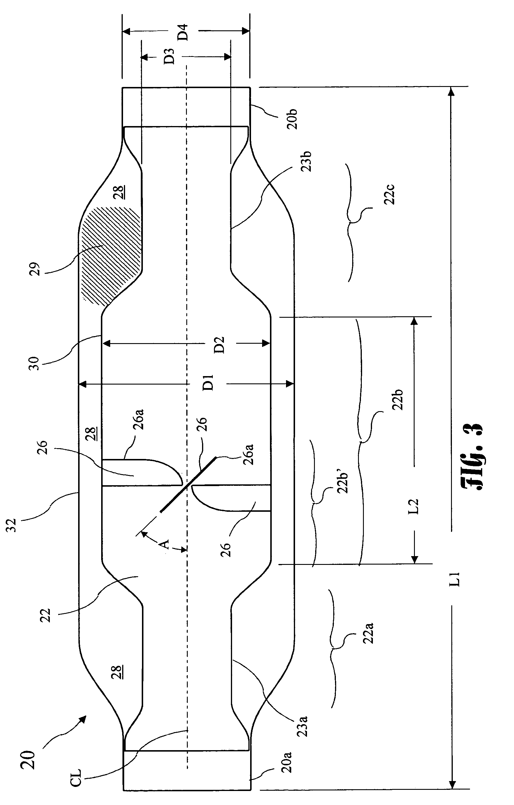
[0021]A side view of the muffler 20 is shown in FIG. 2. A cross-sectional view of the muffler 20 taken along line...


PUM


Abstract

A muffler includes an inner passage residing in an outer shell, and a stationary fan residing in the inner passage. The fan creates a vortex in a flow through the inner passage thus improving the flow and reducing the exhaust sound level. The inner passage includes an inner passage shell and the fan comprises vanes extending inward from the inner passage shell and turned at approximately a 45 degree angle to a centerline of the inner passage. Pinch zones at the entrance and exit from the inner passage further reduce the exhaust sound level. The inner passage shell is preferably a perforated inner passage shell, and a sound deadening material resides between perforated inner passage shell and the outer shell.

Description

BACKGROUND OF THE INVENTION[0001]The present invention relates to improving the efficiency of an internal combustion engine and in particular to a muffler which reduces exhaust system back pressure to improve engine performance.[0002]The increasing cost of oil has motivated car owners and manufacturers to seek means to improve vehicle mileage. In particular, auto manufacturers seek to increase their market share and to satisfy government mileage requirements. Improvements to exhaust systems in the form of reduced restriction and tuned lengths have become commonplace and vehicle mileage has somewhat benefitted from such efforts. However, meeting federally mandated mileage requirements remains a challenge and further improvements are necessary.[0003]Reducing pollution continues to be an important societal objective. Pollution levels in metropolitan areas remain unacceptably high at times, and create an immediate direct health issue for humans, and a longer term issue due to the damage...

Claims


Application Information

Patent Timeline
Patent Type & Authority Patents(United States)
IPC IPC(8): F01N1/08F01N1/12F01N1/02F01N1/04F01N1/10
CPCF01N1/085F01N1/088F01N1/10F01N13/1872F01N2450/22F01N2470/02F01N2490/08
Inventor WALL, ALAN
Owner WALL ALAN
Why Eureka
Try Eureka