Frequency divider with reduced jitter and apparatus based thereon

a frequency divider and jitter reduction technology, applied in the direction of oscillator generators, pulse automatic control, pulse technique, etc., can solve the problems of low signal-to-noise ratio, increased bit error rate, and high interference to neighboring channels, so as to reduce or eliminate jitter and achieve effective and robust technique

Inactive Publication Date: 2005-01-11
ST ERICSSON SA
View PDF7 Cites 23 Cited by
  • Summary
  • Abstract
  • Description
  • Claims
  • Application Information

AI Technical Summary

Benefits of technology

The frequency divider architecture provided herein allows reducing or eliminating jitters of different kinds of circuits, and in particular asynchronous circuits like the zipper divider circuits. The double-reclocking according to the present invention is a very effective and robust technique.

Problems solved by technology

Jitter results from circuit noises that change the transition of signals across the threshold.
Jitter is a major concern in frequency dividers, oscillators, frequency synthesizers, etc. because introducing even a small jitter into these circuits leads to dramatic changes in its frequency spectrum and timing properties, thus resulting in lower signal-to-noise ratio, increased bit error rates, and higher interference to neighboring channels.
Jitter is also important in clocked and sampled-data systems because the zero-crossing often contain information so any uncertainties in switching instants will cause error.

Method used


Image

  • Frequency divider with reduced jitter and apparatus based thereon
  • Frequency divider with reduced jitter and apparatus based thereon
  • Frequency divider with reduced jitter and apparatus based thereon

Examples


Embodiment Construction

For sake of simplicity, certain of the signal lines in the various Figures are shown as single ended signal lines. In reality, many of the signals are differential, meaning that there are in fact two signal lines. Other signals may be digital signals that are several bits wide.

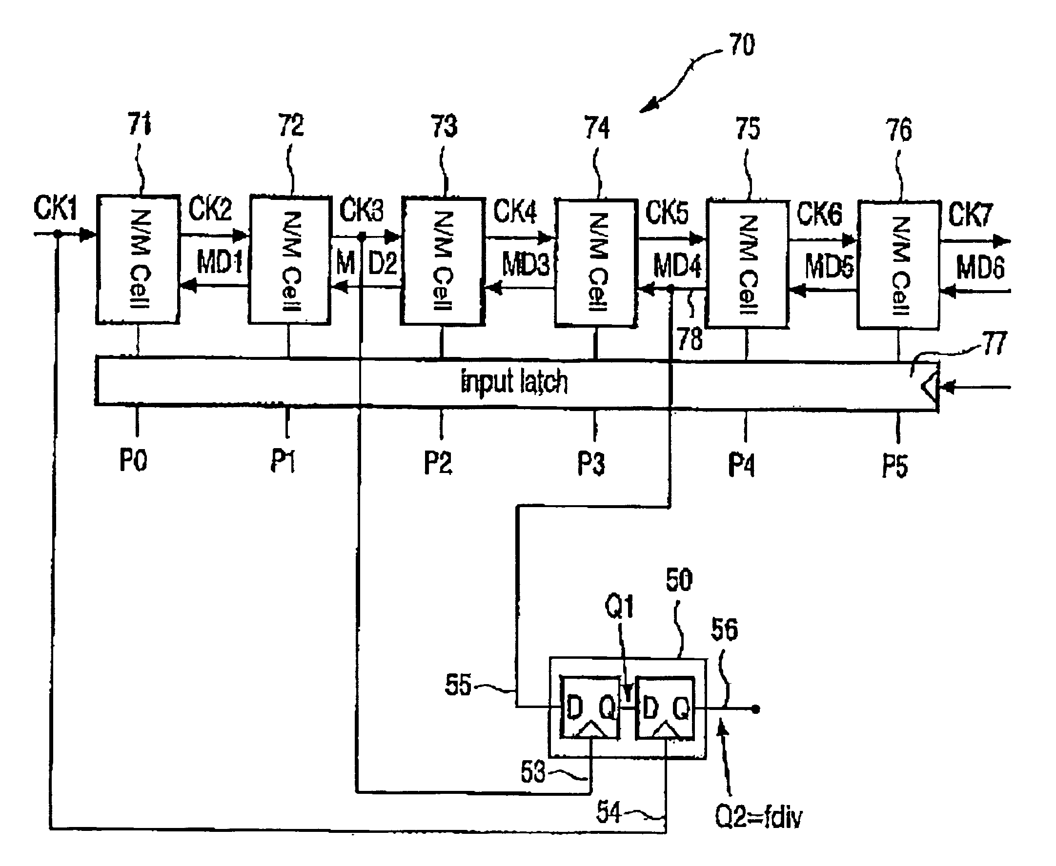
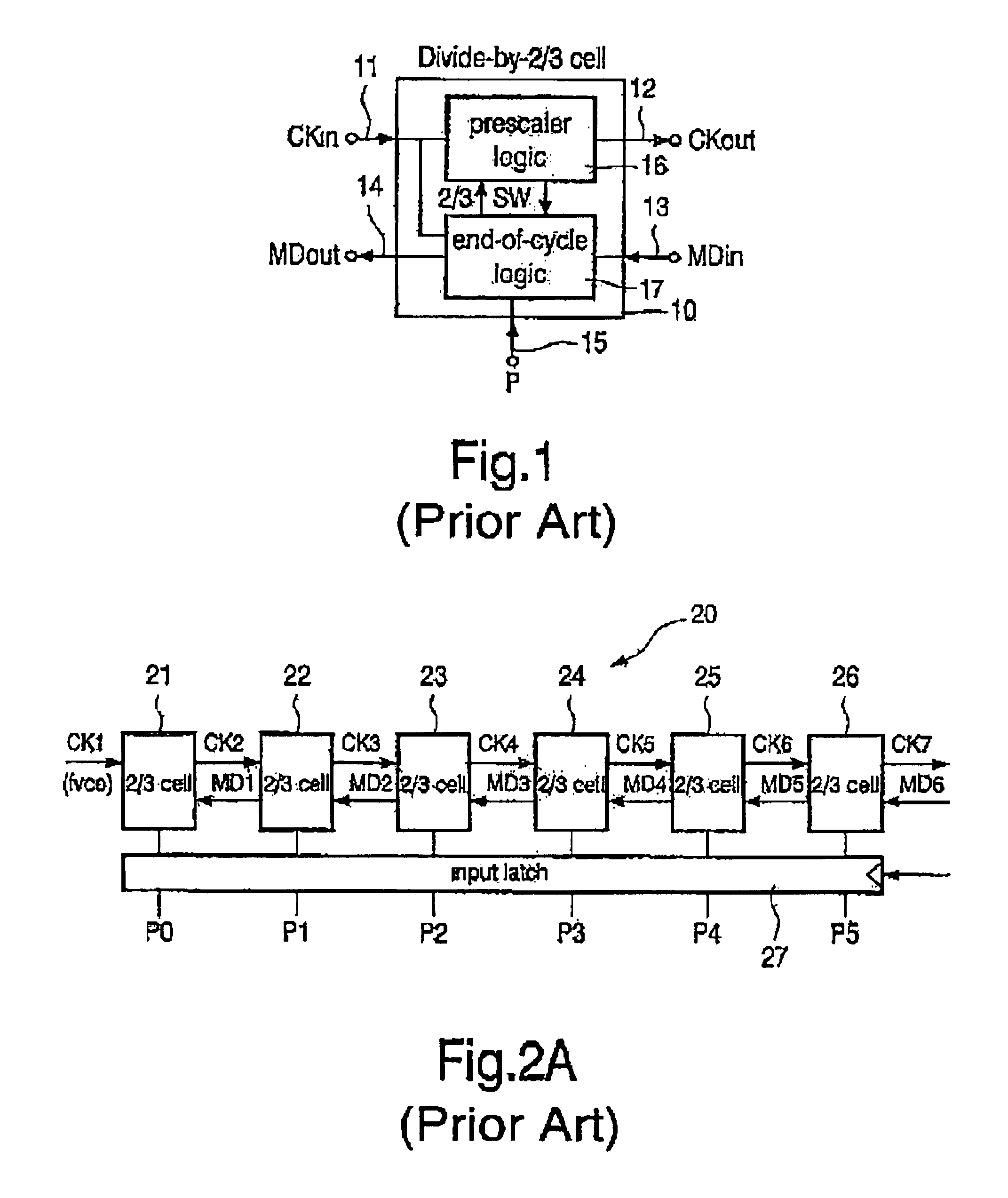
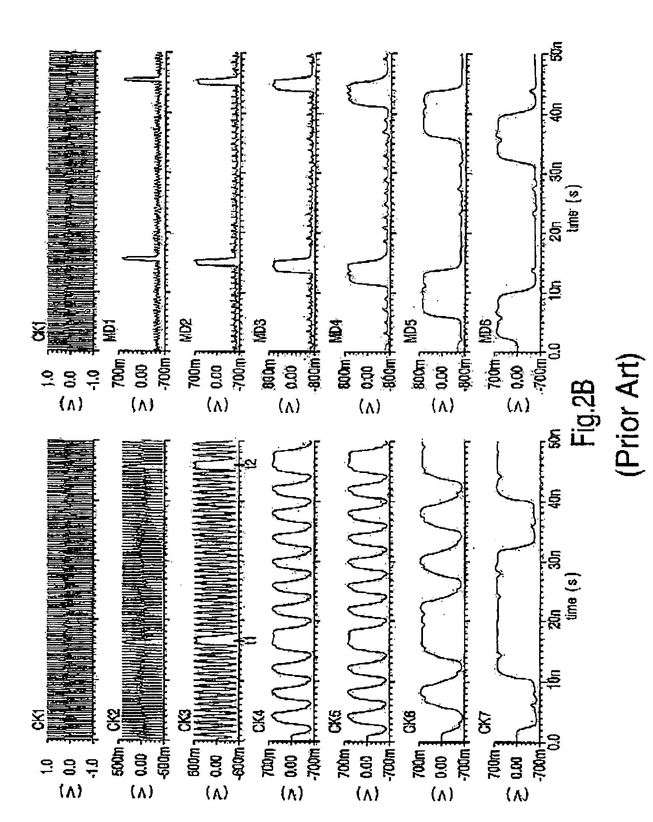
In the following, reference is made to FIGS. 2A and 3. For low-jitter design it would be preferable to take the signal MD1 as the output. Unfortunately, due to some timing constraints the output signal (fdiv) of the divider is often tapped somewhere in the middle of the divider chain 20. For Bluetooth transceivers currently under development, for example, the divider output (fdiv) is tapped at MD4 (c.f. FIG. 3). As a result, jitters at the output (fdiv) may be too large to be accepted in most applications.

It turns out that the known reclocking technique fails in such devices. Reclocking is a technique used to reduce jitter. The reclocking process calls for a less jittery signal to clock a D-Flip-Flop (DFF) 30,...


PUM


Abstract

A circuit generates an output signal whose frequency is lower than the frequency of an input signal. In an example embodiment, there is a chain of frequency dividing cells. Each of the frequency dividing cells has a pre-defined division ratio and a clock input for receiving an input clock, a divided clock output for providing an output clock to a subsequent frequency dividing cell, a mode control input for receiving a mode control input signal from the subsequent frequency dividing cell, and a mode control output for providing a mode control output signal to a preceding frequency dividing cell. Further included are a latch for altering the division ratio of each of the frequency dividing cells and D-Flip-Flop circuitry having two latches. A first signal clocks the first latch and a second signal clocks the second latch, whereby the frequency of the first signal is lower than the frequency of the second signal.

Description

FIELD OF THE INVENTIONThe present invention concerns frequency dividers and apparatus for frequency division. More particularly, this invention relates to a frequency divider architecture and circuit technique based on the zipper divider architecture being well suited for use in transmitters and receivers, in particular for radio frequency signal transmission.BACKGROUND OF THE INVENTIONGreat efforts have been made in radio frequency (RF) design towards one-chip transceivers in standard complementary metal oxide semiconductor (CMOS) in recent years. Particularly the CMOS implementation of frequency dividers and frequency synthesizers—one of the key building blocks in a transceiver—have attracted a lot of attention. The most notable trend here is the zipper divider architecture and the so-called current-mode logic (CML).The known zipper divider is comprised of a chain of divide-by-⅔ cells of identical circuitry. Shown in FIG. 1 is a conventional divide-by-⅔ cell 10 having five termina...

Claims


Application Information

Patent Timeline
Patent Type & Authority Patents(United States)
IPC IPC(8): H03K23/66H03K23/00H03L7/197H03L7/16H03K23/64
CPCH03L7/1976H03K23/667
Inventor WANG, ZHENHUA
Owner ST ERICSSON SA
Why Eureka
Try Eureka