Positive station module locking mechanism for expandable irrigation controller

a technology of expandable irrigation controller and locking mechanism, which is applied in the direction of electrical apparatus casing/cabinet/drawer, coupling device connection, instruments, etc., can solve the problems of springs that require considerable force to be exerted by users, springs can also break, and water pressure fluctuations that cannot be fully negated

Inactive Publication Date: 2005-01-11
HUNTER INDUSTRIES
View PDF17 Cites 107 Cited by
  • Summary
  • Abstract
  • Description
  • Claims
  • Application Information

AI Technical Summary

Benefits of technology

In accordance with the present invention a modular expandable irrigation controller has controls for manual entry or selection of a watering program and a memory for storing the watering program. A processor executes the stored watering program and controls one or more station modules each including a station module circuit for ener...

Problems solved by technology

The amount of water supplied by each sprinkler is largely determined by the size and configuration of its nozzle orifice(s), although variations result from fluctuations in water pressure that cannot be fully negated with regulators.
However, such springs often require considerable force to be exerted by the user, both during installation and w...

Method used


Image

  • Positive station module locking mechanism for expandable irrigation controller
  • Positive station module locking mechanism for expandable irrigation controller
  • Positive station module locking mechanism for expandable irrigation controller

Examples


first embodiment

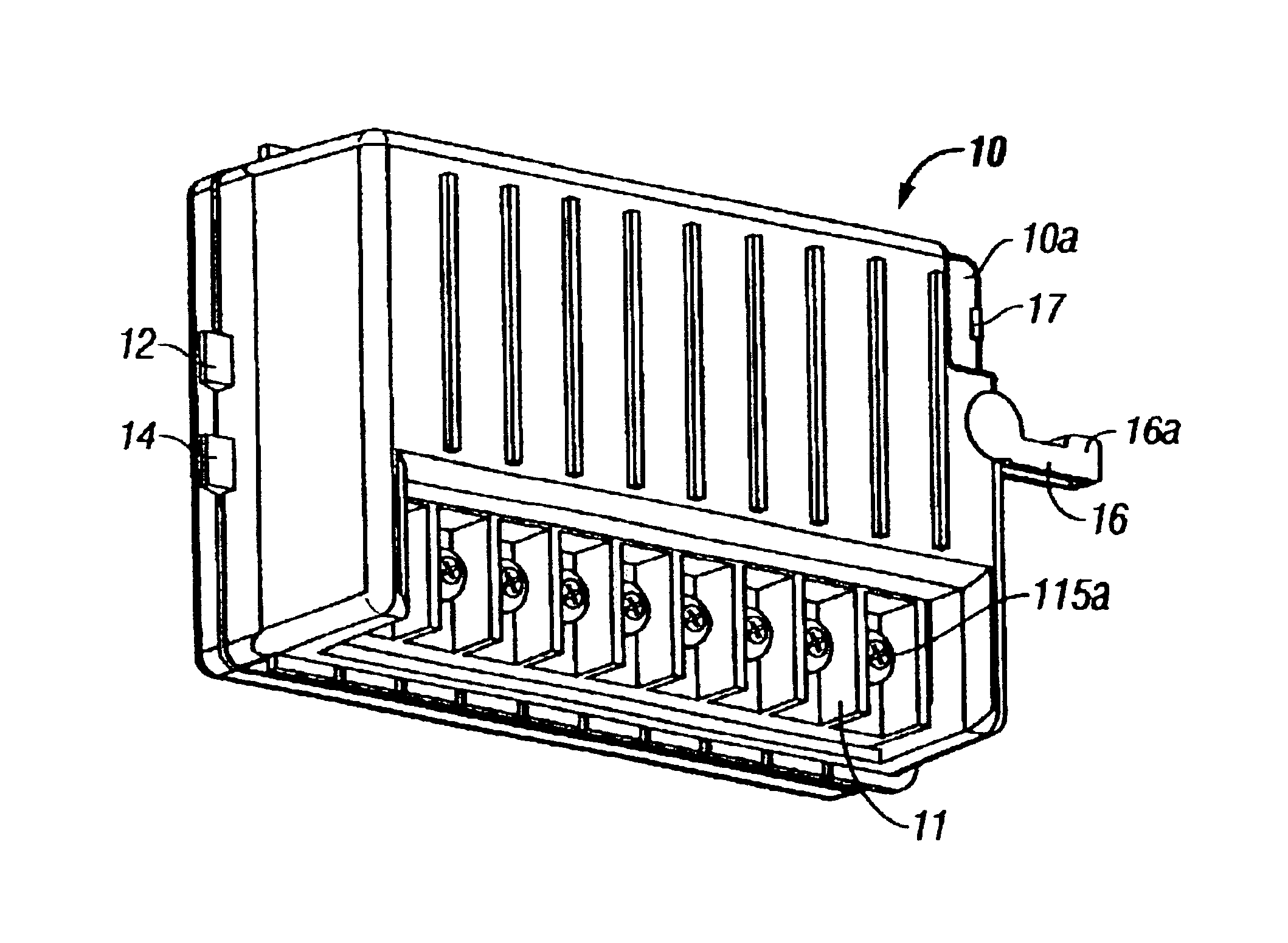
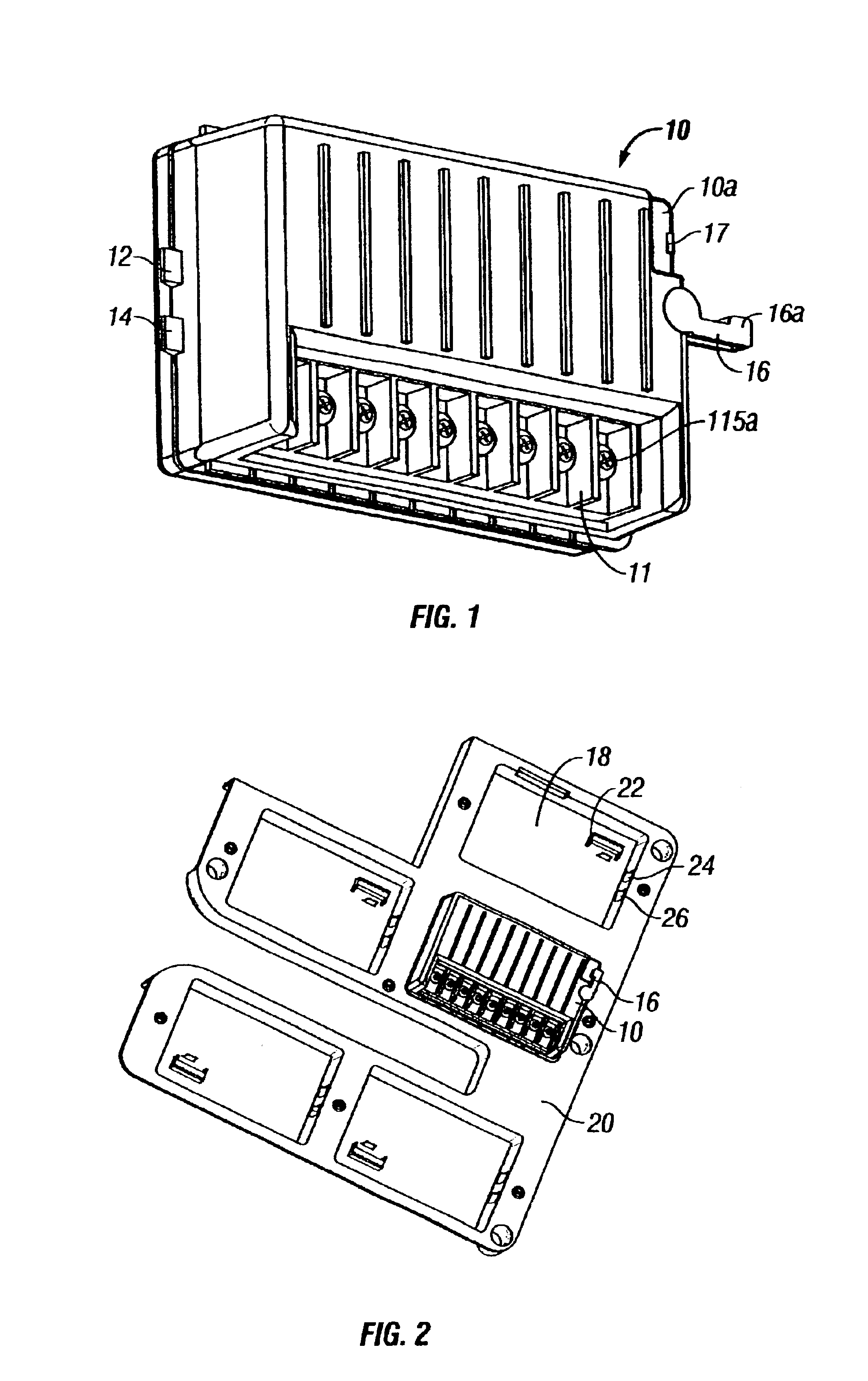
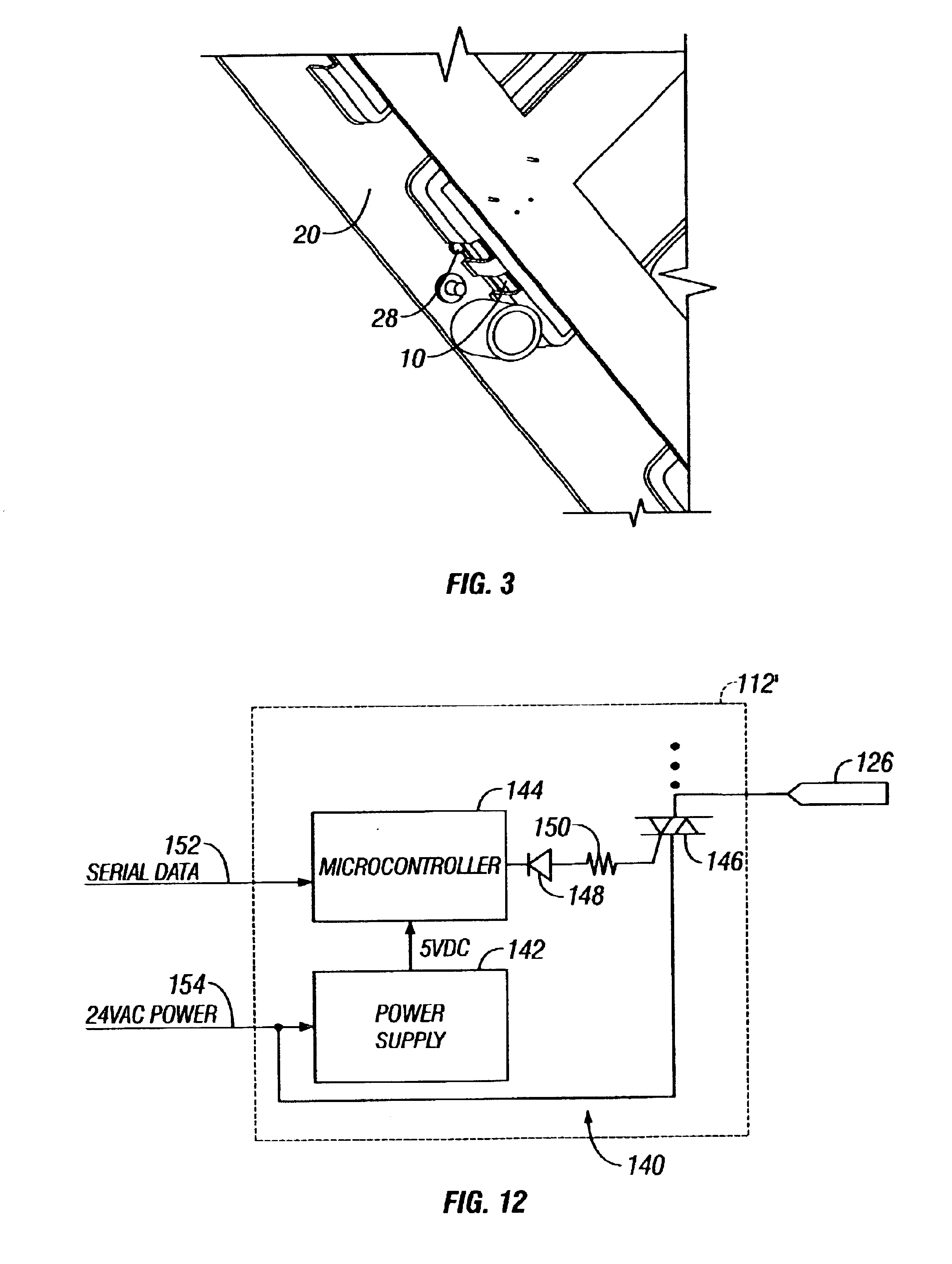
Referring to FIGS. 1-3, in accordance with our invention, a rectangular station module 10 has a pair of rigid (non-resilient) wedge-shaped tabs 12 and 14 that project from one end and a pivotable locking lever 16 that is mounted at the opposite end. The station module 10 is inserted into a receptacle such as 18 (FIG. 2) formed in the back panel 20 that is hinged to a separate housing (not shown) that contains the microprocessor. During the insertion of the station module 10 into the receptacle 18, the left end of the station module is first lowered into the receptacle 18 so that the wedge-shaped tabs 12 and 14 are inserted into corresponding side-by-side rectangular apertures in one end wall of the receptacle 18, which are similar to the two apertures 24 and 26 in the opposite end wall. The right end of the station module 10 is then lowered into the receptacle 18. At this time pins (not shown) on the back side of the station module 10 are plugged into corresponding holes in a female...

second embodiment

our invention is illustrated in FIGS. 4-9. Referring to FIG. 7, female electrical connectors 29 in the ends of three box-like station modules 30, 32 and 34 receive corresponding card edge connectors such as 36 (FIG. 5) with mating electrical contacts. The station modules 30, 32 and 34 are received in side-by-side fashion in a bay formed in a rectangular back panel 38 (FIG. 4) that is separate from the housing (not illustrated) that encloses the microprocessor. A larger, fourth box-like power module 40 (FIG. 6) plugs into the bay onto its own card edge connector and drives the pump master valve and the first three station modules 30, 32 and 34. The upper sides of the modules 30, 32, 34 and 40 each have an upstanding projection 42 (FIG. 6). A locking slide bar 44 (FIG. 8) with a V-shaped gripping member 46 extends above the bay and may be slid laterally (left and right) between an unlocked position illustrated in FIG. 6 and a locked position illustrated in FIG. 7. A V-shaped bump 48 (...


PUM


Abstract

A modular expandable irrigation controller has controls for manual entry or selection of a watering program and a memory for storing the watering program. A processor executes the stored watering program and controls one or more station modules each including a station module circuit for energizing at least one solenoid actuated valve in accordance with the watering program. The irrigation controller has a plurality of receptacles for each removably receiving a station module and for providing an operative connection to the processor. A manually movable locking member is grasped and moved between UNLOCKED and LOCKED positions to positively secure each station module in a corresponding receptacle.

Description

FIELD OF THE INVENTIONThe present invention relates to electronic irrigation controllers that control valves which supply water to sprinklers, and more particularly, to modular expandable irrigation controllers.BACKGROUND OF THE INVENTIONIn many parts of the world due to inadequate rainfall it is necessary at some times during the year to artificially water turf and landscaping. An ideal irrigation system for turf and landscaping should utilize a minimum number of valves, supply lines and sprinklers. Preferably the valves should be turned ON and OFF by an inexpensive, yet reliable electronic irrigation controller that is easy to program and can carry out a wide variety of watering schedules. The goal is to uniformly distribute the optimum amount of water over a given area. Rotor type sprinklers have largely displaced older impact type sprinklers in applications where large expanses of grass are watered, such as golf courses, due to the fact that the former are more reliable, quieter...

Claims


Application Information

Patent Timeline
IPC IPC(8): A01G25/16
CPCA01G25/165Y10T137/86389
Inventor BEUTLER, MATTHEW G.ANUSKIEWICZ, RONALD H.MCKNIGHT, JAMES F.UCCELLO, SANTO
Owner HUNTER INDUSTRIES
Why Eureka
Try Eureka