
Anti-tip arrangement for a mobile storage system

a mobile storage and anti-tip technology, applied in the direction of rope railways, sectional furniture, furniture parts, etc., can solve the problems of obstructing the access of the hook member, the anti-tip retainer section is complicated, and the carriage components are complicated, so as to facilitate the movement of the anti-tip member, reduce the overall height of the rail, and facilitate the effect of anti-tip member movemen

Inactive Publication Date: 2005-01-18
SPACESAVER
View PDF8 Cites 19 Cited by
  • Summary
  • Abstract
  • Description
  • Claims
  • Application Information

AI Technical Summary

Benefits of technology

In another construction, the rail includes an upwardly facing base or channel to which a support bar is mounted, to reduce the overall height of the rail. The channel includes a lip that extends inwardly toward the support bar. An anti-tip arrangement for this type of rail construction utilizes a C-shaped anti-tip member that is engaged with the carriage after the carriage is mounted to the rail. The anti-tip member includes an upper section that is mounted to the carriage, and a lower section that is received within the space defined between the lip of the channel and the lower wall of the channel, to prevent the carriage from tipping relative to the rail. While this arrangement is functional, it is disadvantageous in that the anti-tip member is separate from the carriage and is mounted to the carriage after the carriage is mounted to the rail.
It is an object of the present invention to provide an anti-tip arrangement for a mobile system, such as a mobile storage system, which provides quick and easy movement of an anti-tip member from an inoperative position to an operative position when the movable member is mounted to the support surface of the rail arrangement. It is a further object of the invention to provide such an anti-tip arrangement in which the anti-tip member is carried by the movable member, to eliminate the need for a separate anti-tip member which is engaged with the movable member subsequent to placement of the movable member on the rail arrangement. It is a further object of the invention to provide such an anti-tip arrangement in which separate areas of the anti-tip member are employed to move the anti-tip member to its operative position and to engage a releasable retainer arrangement with the anti-tip member for releasably retaining the anti-tip member in its operative position. Yet another object of the invention is to provide such an anti-tip arrangement which takes advantage of a channel-type rail construction for facilitating movement of the anti-lip member from its inoperative position toward its operative position.

Problems solved by technology

The retainer section of the anti-tip member is located over the rail, and access to the retainer section of the anti-tip member is complicated by the components of the carriage located vertically above the retainer section of the anti-tip member.
The hook section is accessible from the side, which is also complicated by the components of the carriage.
In addition, the hook member is located within a space defined between the rail and a base member to which the rail is mounted, and the base obstructs access to the hook member.
Thus, in either case, it is difficult for a user to manipulate the retainer section of the anti-tip member in order to move the anti-tip member from the disengaged position to the engaged position, and to simultaneously engage the retainer pin with the retainer section of the anti-tip member when the anti-tip member is in the operative position.
While this arrangement is functional, it is disadvantageous in that the anti-tip member is separate from the carriage and is mounted to the carriage after the carriage is mounted to the rail.

Method used


Image

  • Anti-tip arrangement for a mobile storage system
  • Anti-tip arrangement for a mobile storage system
  • Anti-tip arrangement for a mobile storage system

Examples


Embodiment Construction

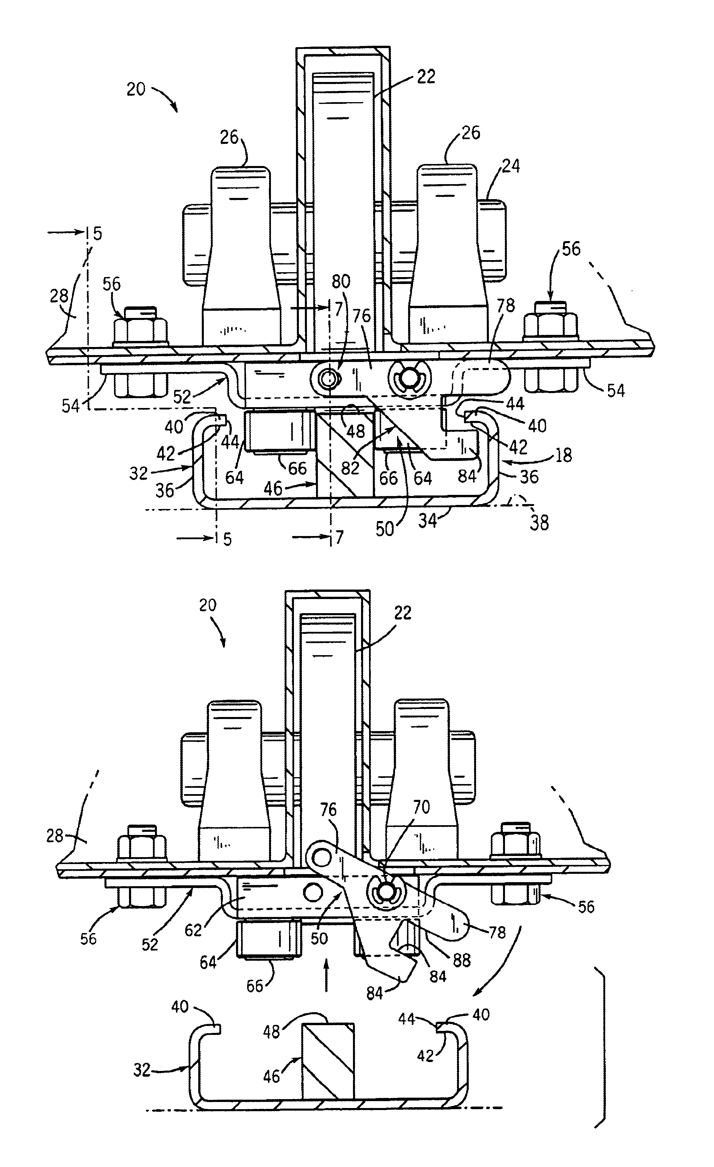
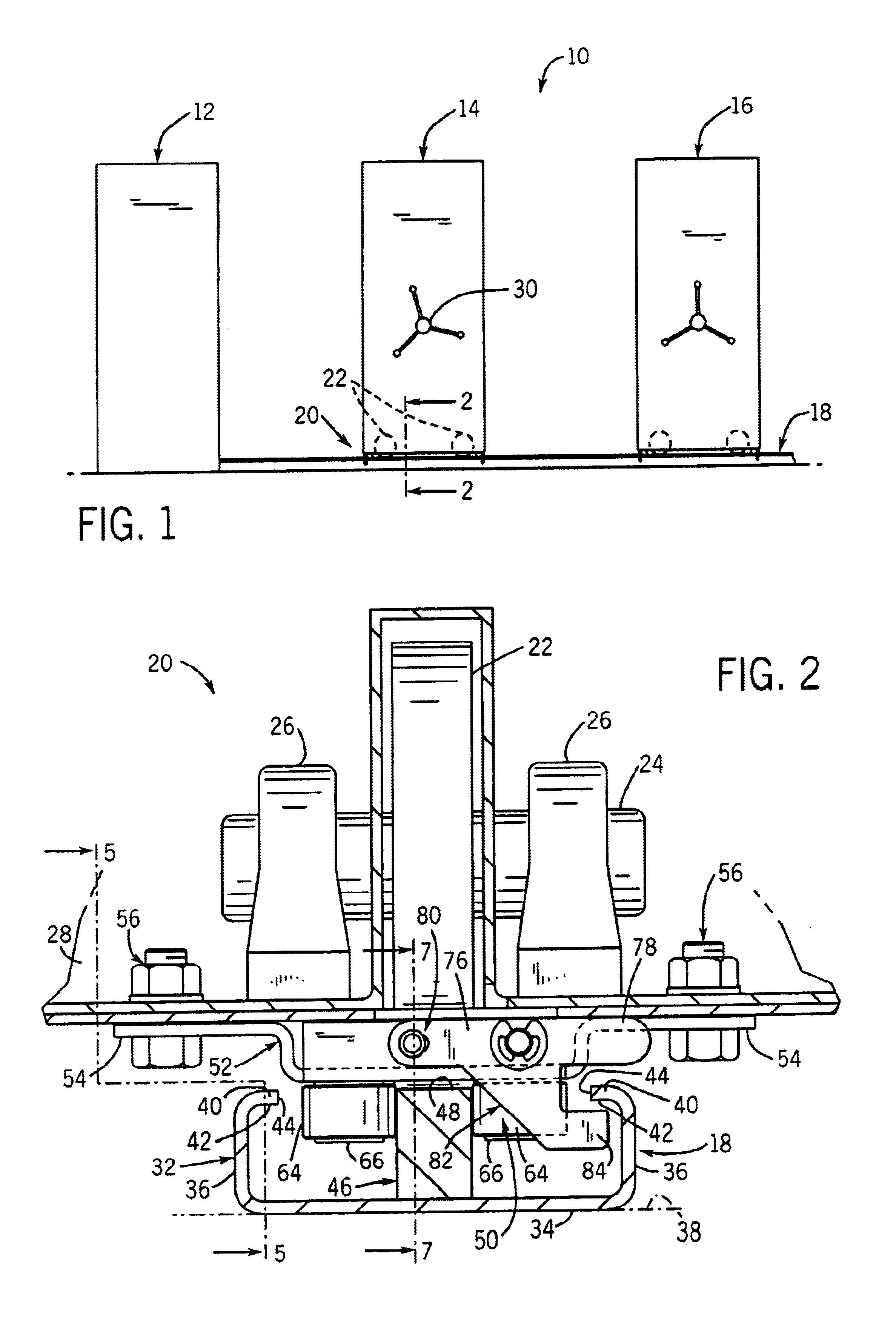
As shown in FIG. 1, a mobile system, in the form of a mobile storage system 10, includes a series of storage units 12, 14 and 16. Storage unit 12 is stationary, and storage units 14 and 16 are movably supported on a series of parallel, spaced apart rails 18 in a manner as is generally known. Storage units 14, 16 are movable on rails 18 together and apart, to selectively create an aisle or space for providing access to the contents of storage units 12, 14 and 16. Representatively, the general construction and operation of mobile storage system 10 is similar to that of mobile storage systems such as are available from Spacesaver Corporation of Fort Atkinson, Wis.

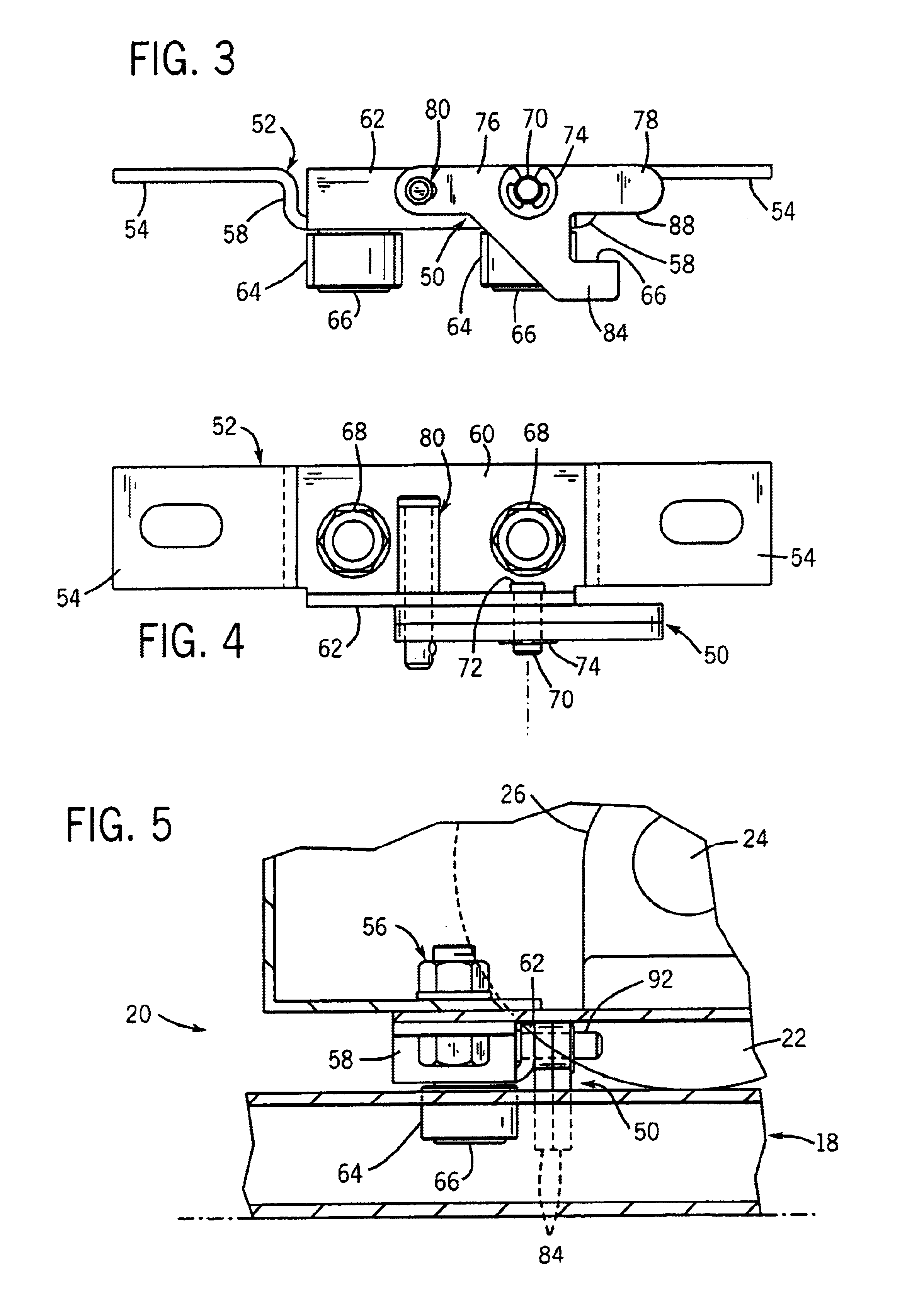
Each of mobile storage units 14, 16 includes a carriage 20, the lower portion of which is shown in FIG. 2. In accordance with known construction, each carriage 20 spans across the parallel rails 18 for movably supporting the storage units 14, 16 on rails 18. Each carriage 20 includes a series of wheels 22, each of which is mou...


PUM


Abstract

An anti-tip arrangement for a mobile system, such as a mobile storage system, in which a movable member is mounted to a rail arrangement. The anti-tip arrangement includes an anti-tip member which is pivotably mounted to the movable member for movement between an operative position and an inoperative position. The anti-tip member has a hook section that is engageable with an engagement surface of the rail arrangement, for preventing tipping of the movable member relative to the rail arrangement. The anti-tip member further includes a retainer section and a tab section that extend in opposite directions from the pivot axis about which the anti-tip member is pivotable. The tab section extends laterally from the pivot axis, and is engageable by a user to enable the user to pivot the anti-tip member to the operative position. The retainer section is offset from the tab section, and is adapted to receive a releasable retainer member, such as a retainer pin, which maintains the anti-tip member in the operative position. The offset of the tab section from the retainer section facilitates the ability of the user to manipulate the anti-tip member for movement to the operative position while engaging the retainer pin with the retainer section.

Description

BACKGROUND AND SUMMARY OF THE INVENTIONThis invention relates to a rail-mounted mobile system such as a mobile storage system, and more particularly to an anti-tip arrangement for such a system.A rail-mounted mobile system, such as a mobile storage system, includes one or more movable members supported on a series of spaced apart parallel rails. In a mobile storage application, the movable members are typically in the form of carriages having wheels that are supported on the spaced apart rails. A series of storage units, such as shelves or cabinets, are mounted to each carriage.Various anti-tip arrangements are known for preventing the carriage-mounted storage units from tipping relative to the rails. One example of such an anti-tip arrangement is shown and described in Peterman U.S. Pat. No. 4,618,191, the disclosure of which is hereby incorporated by reference. The '191 patent discloses an anti-tip system in which a groove is formed in the side of the rail. An anti-tip member is c...

Claims


Application Information

Patent Timeline
IPC IPC(8): A47B53/02A47B53/00
CPCA47B53/02A47B2097/008
Inventor KEATON, WILLIAM R.
Owner SPACESAVER
Learn More