Personal watercraft having a preformed rub rail

a technology of personal watercraft and rub rail, which is applied in the field of personal watercraft, can solve the problems that most vertical bond lines do not provide an upper ridge, injection molds cannot be easily used to form certain lateral or transverse shapes, and injection molding cannot be easily used to form profiles that cannot be pulled from molds

Inactive Publication Date: 2005-01-18
POLARIS IND INC
View PDF11 Cites 28 Cited by
  • Summary
  • Abstract
  • Description
  • Claims
  • Application Information

AI Technical Summary

Benefits of technology

A polymeric rub rail including a vertical portion can be secured to the top deck downwardly extending portion and have an inwardly extending lip disposed beneath the top deck bottom edge, and further have a bottom lip curved upward and inward from the rub rail toward the bottom hull. Some rub rails have a first wing extending downwardly from the rub rail vertical portion and a second wing extending upwardly from the rub rail vertical portion to form an open channel between the wings and the vertical portion. The converging wings can provide resiliency to the rub rail. In some watercraft, the rub rail is formed of a polymeric material having a Shore A hardness of at least about 90. In other watercraft, the rub rail is formed of a polymeric material having a Shore A hardness of at least about 95. The rub rail can be secured to the top deck over a region having a vertical radius of curvature of less than about 20, 15, or 10 inches, depending on the embodiment.

Problems solved by technology

Injection molds cannot easily be used to form certain lateral or transverse shapes.
In particular, injection molding cannot easily be used to form a profile that cannot be pulled from the mold, for example, profiles having a central channel or converging cantilevered wings.
Most vertical bond lines do not provide an upper ridge on which to hang or support the rub rail.
Rigid rub rails can present a problem in that they do not conform to complex surface geometries as easily as semi-rigid or flexible.
In particular, vertically curved or bow lines have been difficult to protect with rigid rub rails.
Also, rear corners have been difficult to protect with rigid rub rails.
Injection molding suffers from the cost disadvantage discussed above.
Injection molding also can limit the rub rail to shapes that have limited resiliency.

Method used


Image

  • Personal watercraft having a preformed rub rail
  • Personal watercraft having a preformed rub rail
  • Personal watercraft having a preformed rub rail

Examples


Embodiment Construction

The following detailed description should be read with reference to the drawings, in which like elements in different drawings are numbered identically. The drawings, which are not necessarily to scale, depict selected embodiments and are not intended to limit the scope of the invention. Several forms of invention will be shown and described, and other forms will now be apparent to those skilled in art. It will be understood that the embodiments shown in the drawings and described below are merely for illustrative purposes, and are not intended to limit the scope of the invention as defined in the claims that follow.

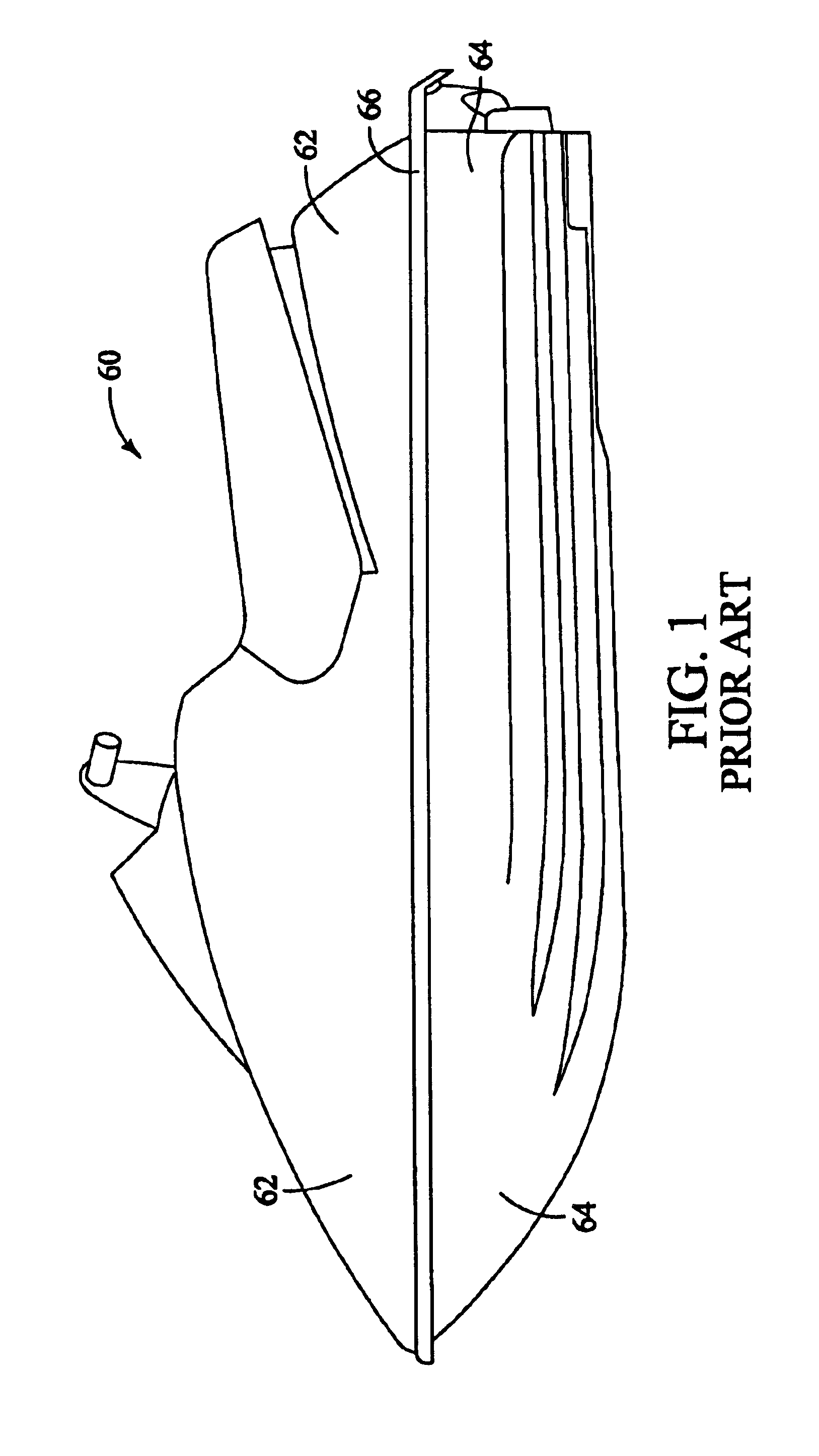
FIG. 1 illustrates a prior art personal watercraft 60 having generally a top deck 62, a bottom hull 64, and a substantially, vertically straight side rub rail 66. While the rub rail of personal watercraft 60 may wrap around shallow, horizontal curves of the top deck, little vertical curvature is seen.

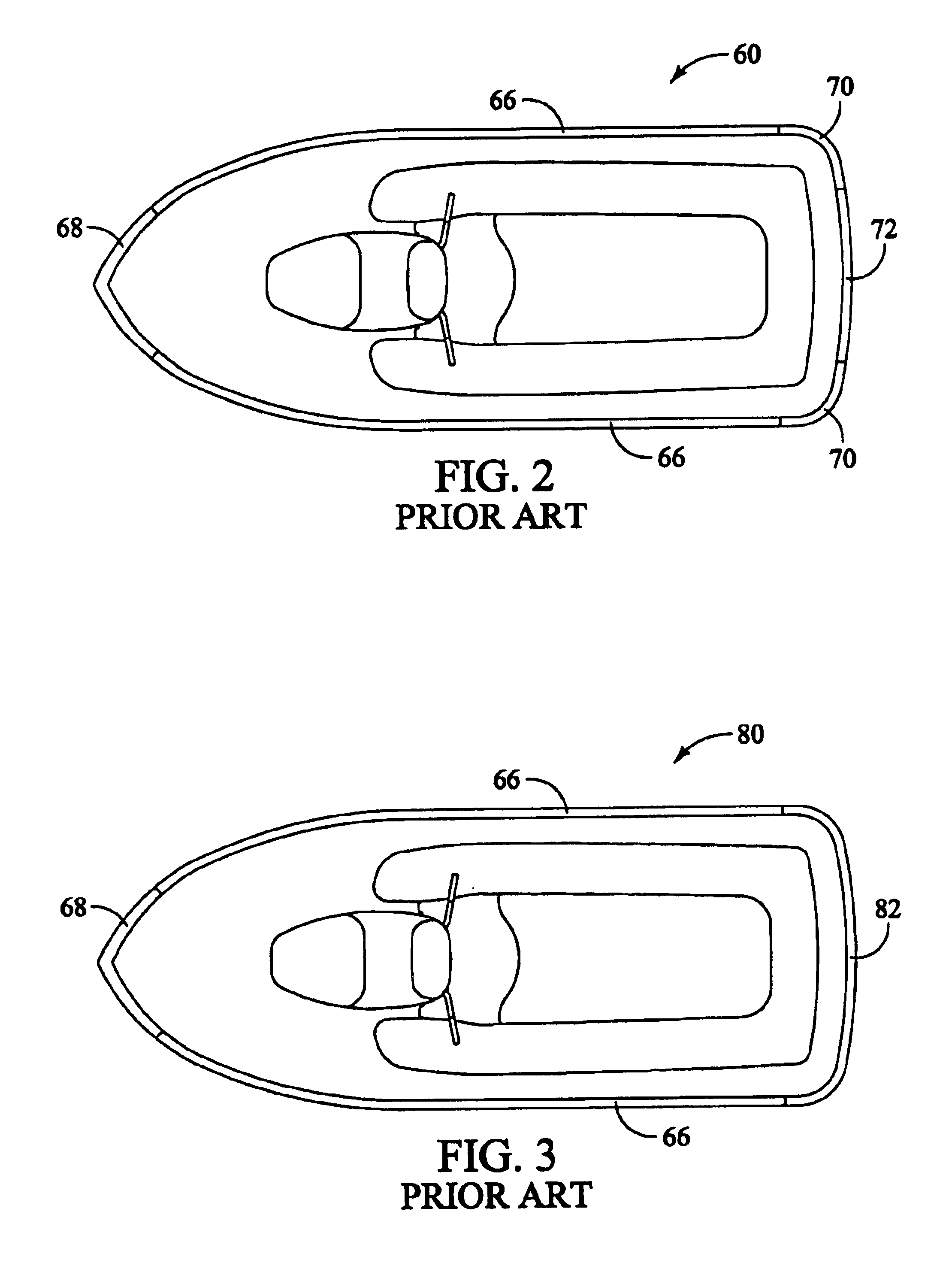
FIG. 2 illustrates personal watercraft 60 of FIG. 1 from the top. Perso...


PUM


Abstract

Personal watercraft having extruded rigid rub rails that can be curved in vertical and horizontal dimensions to provide complex geometries in watercraft. One rub rail has a pair of resilient opposed converging wings extending outwardly from the rub rail to form an open channel along the rub rail length. A first bottom lip can extend inwardly to hug the downwardly facing surface of the top deck. A second lip can curve upward and inward beneath the first inwardly extending bottom lip. The second lip can provide an increased ability to hug sharp horizontally curved corners of the watercraft without wrinkling, for example, the rear corners of the watercraft. The rub rail can be both vertically and horizontally curved in the same region and be affixed to a vertical bond flange. In some personal watercraft, the rub rail is formed of a rigid material having a Shore A hardness of at least about 90. The complex geometries of some rub rails are created by heating the rub rail, securing the rub rail to a forming jig or fixture, and allowing the rub rail to cool. The cooled rub rail can thus have the preformed, complex geometry of the top deck to which it is to be affixed, while having a transverse profile than cannot be made by injection molding.

Description

FIELD OF THE INVENTIONThe present invention is related generally to personal watercraft. More specifically, the present invention is related to rub rails on personal watercraft.BACKGROUND OF THE INVENTIONPersonal watercraft (PWC) have become increasingly popular in recent years. A personal watercraft, also known as a “jet ski” typically has a bottom hull, handle bars for steering, a tunnel within the bottom hull, a jet pump located within the bottom tunnel, and an engine within the hull under the top deck for driving the jet pump. The jet pump typically pulls in water from the front of the tunnel under the boat, and discharges the water at high velocity through a steerable nozzle at the rear of the boat. The handlebars are typically coupled to the nozzle, which is the steering mechanism for the personal watercraft. The watercraft commonly has a straddle-type seat and foot wells disposed on either side of the seat.Personal watercraft typically have a top deck affixed to a bottom hull...

Claims


Application Information

Patent Timeline
Patent Type & Authority Patents(United States)
IPC IPC(8): B63B59/02B63B59/00B63B35/73
CPCB63B59/02B63B35/731B63B34/10
Inventor NUGTEREN, DANTHOMPSON, JOHN
Owner POLARIS IND INC
Why Eureka
Try Eureka