Hermetically sealed current conducting terminal assembly

a current conducting terminal and hermetically sealed technology, applied in hermetically sealed casings, electrical apparatus casings/cabinets/drawers, coupling device connections, etc., can solve the problems of comparatively high cost and difficult manufacturing of the terminal assemblies described abov

Inactive Publication Date: 2005-01-18
EMERSON ELECTRIC CO
View PDF59 Cites 23 Cited by
  • Summary
  • Abstract
  • Description
  • Claims
  • Application Information

AI Technical Summary

Benefits of technology

In one aspect of the invention, the terminal assembly comprises a multi-component, current conducting pin assembly having a first pin member and a second pin member that are joined at a core. In at least some embodiments of the invention, the core physically and / or electrically connects the first and second pin members of the pin assembly. An annular sleeve is axially disposed around pin assembly. The pin assembly is fused to the annular sleeve by a glass-to-metal seal that provides a first electrically insulating hermetic seal between the pin assembly and the annular sleeve. In addition, first and second sleeves are disposed over the first and second pin members on opposite sides of the core to provide a second electrically insulating seal and oversurface protection between the pin assembly and the annular sleeve.

Problems solved by technology

The terminal assemblies described above may be comparatively expensive and difficult to manufacture.

Method used


Image

  • Hermetically sealed current conducting terminal assembly
  • Hermetically sealed current conducting terminal assembly
  • Hermetically sealed current conducting terminal assembly

Examples


first embodiment

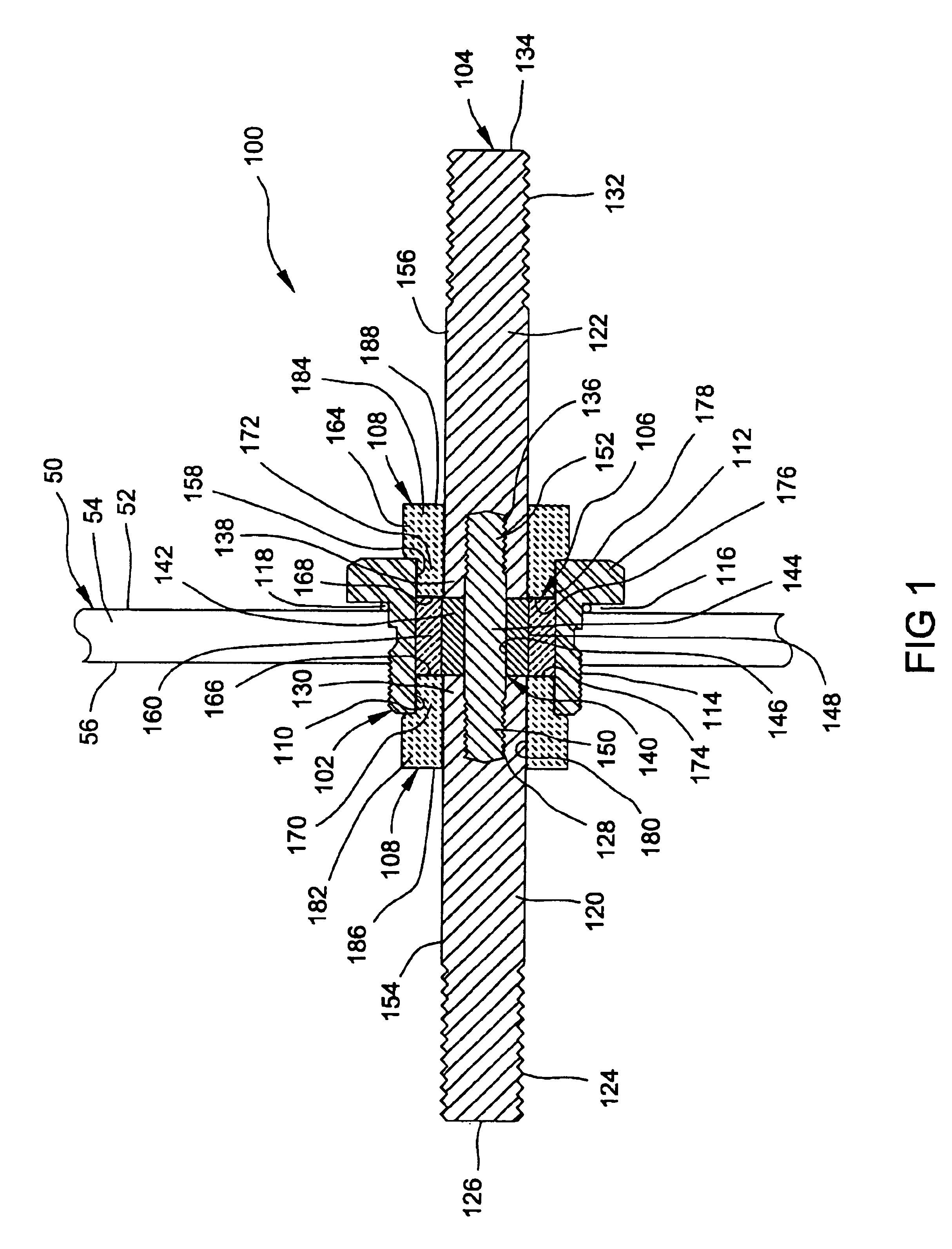
With particular reference to FIG. 1, the hermetically sealed current conducting pin installation 100 is shown as including an annular sleeve 102, a pin assembly 104, a hermetic seal 106, and a second electrical insulator 108.

The annular sleeve 102 is a substantially cylindrical member having a bore 110, an axial flange 112 at a first end, and a threaded portion having threads 114 adapted to matingly engage corresponding threads of a larger opening in a housing 50. The junction of the threaded portion and the axial flange 112 cooperate to form an axial recess 116 where an O-ring 118 is disposed for engagement with an outer wall of the housing 50 to create a seal. While an O-ring 118 is disclosed, any suitable gasket could be used to adequately seal the outer surface of the housing wall and the axial flange 112 of the annular sleeve 102 and should be considered within the scope of the invention.

The pin assembly 104 includes a first longitudinal pin member 120 and a second longitudinal...

second embodiment

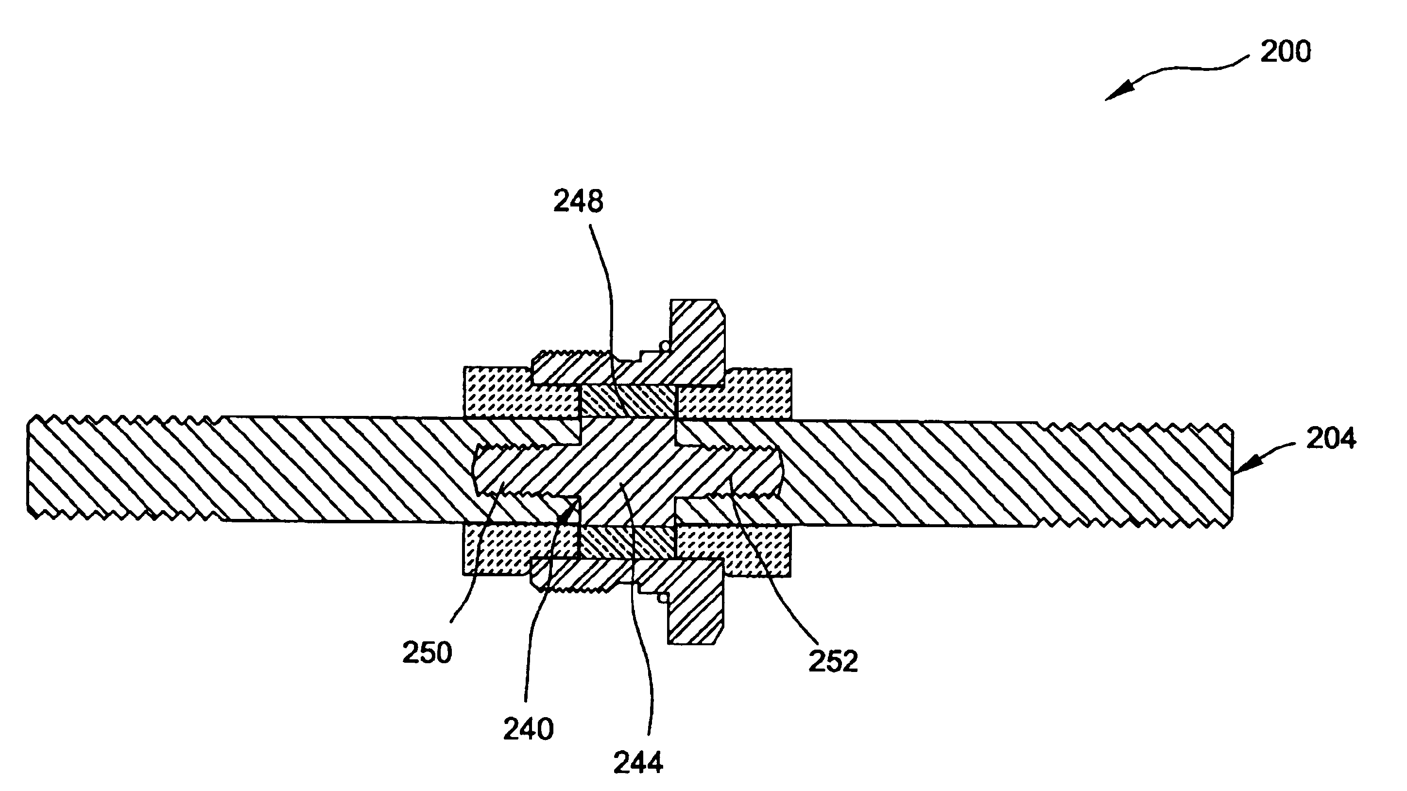
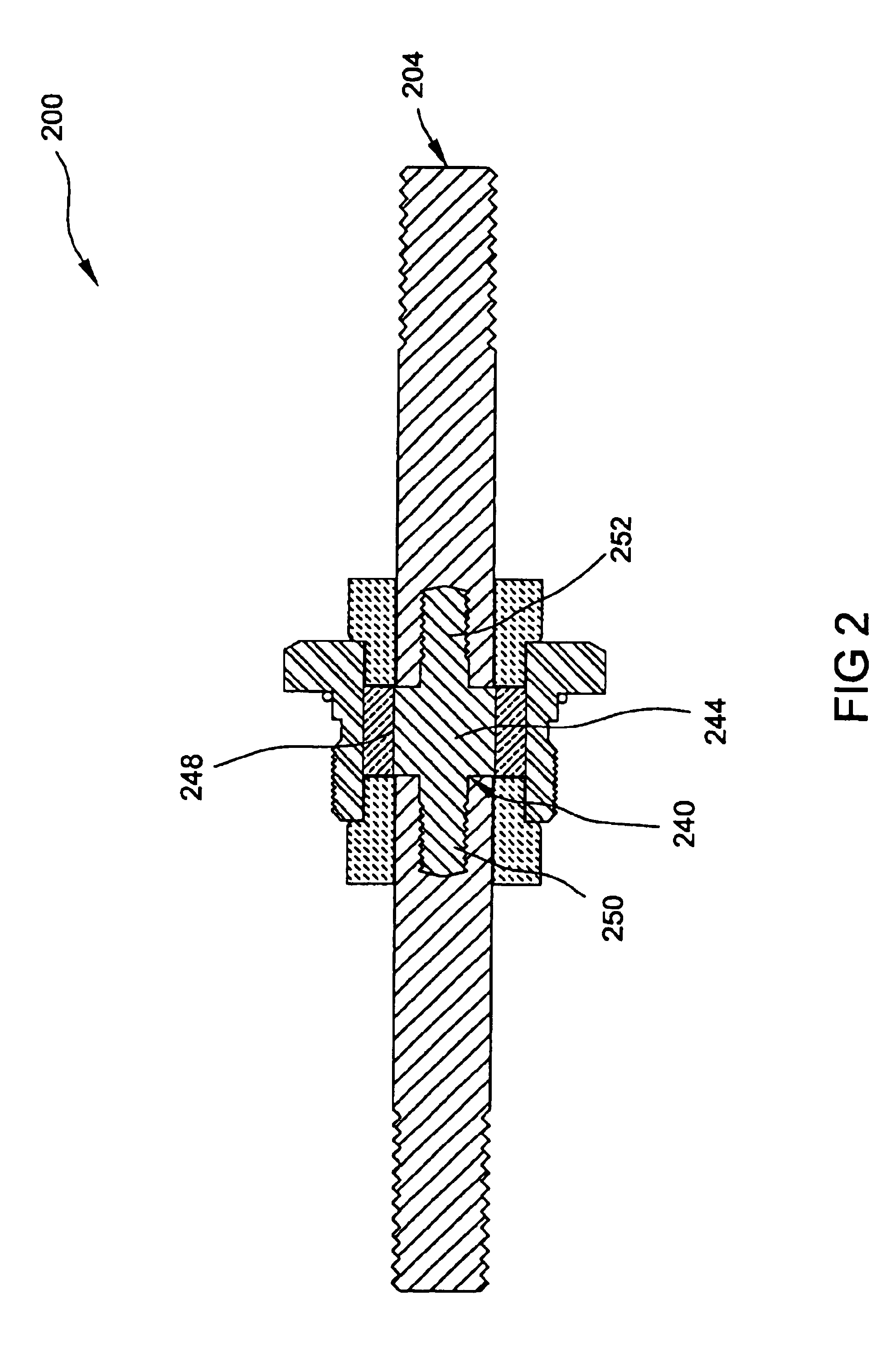
With particular reference to FIG. 2, the hermetically sealed current conducting pin installation 200 is shown having an annular sleeve 102, first and second insulators 106, 108, and a pin assembly 204.

In general, the hermetically sealed current conducting pin installation 200 is substantially similar to the hermetically sealed current conducting pin installation 100 described above. In view of the substantial similarity in structure and function of the components associated with the hermetically sealed current conducting pin installation 100 and the hermetically sealed current conducting pin installation 200, like reference numerals are used here and in the drawings to identify like components.

The pin assembly 204 of this embodiment comprises a core 240 having unitary construction, including a central cylindrical collar portion 244 and first and second extension portions or studs 250, 252. The central collar portion 244 has an outer surface 248 that is generally equivalent to that o...

third embodiment

With particular reference to FIG. 3, the hermetically sealed current conducting pin installation 300 is shown having an annular sleeve 102, a first and second insulators 106, 108, and a pin assembly 304.

The hermetically sealed current conducting pin installation 300 is substantially similar to the hermetically sealed current conducting pin installation 100 described above. In view of the substantial similarity in structure and function of the components associated with the hermetically sealed current conducting pin installation 100 and the hermetically sealed current conducting pin installation 300, like reference numerals are used here and in the drawings to identify like components.

The pin assembly 300 has a core 340 comprising a cylindrical collar 341 that includes first and second blind threaded bores 390, 392 and an outer surface 348. The outer surface 348 is generally the same in diameter as the diameters of pin members 320, 322 of the pin assembly 304. The core 340 is attache...


PUM

PropertyMeasurementUnit
electrically insulatingaaaaaaaaaa
outer diameteraaaaaaaaaa
electrical conductoraaaaaaaaaa

Abstract

A hermetically sealed current conducting terminal assembly for installation in an opening in the wall of a housing. The terminal assembly includes a current conducting pin assembly comprising a first pin member electrically connected to a second pin member at a conductive core and a first and second seal that electrically isolate the pin assembly from the housing.

Description

FIELD OF THE INVENTIONThe present invention relates to hermetically sealed, current conducting terminal assemblies suitable for installation in an opening in the wall of a housing.BACKGROUND OF THE INVENTIONIt is known to provide a hermetically sealed, current conducting terminal assembly that can be installed in a housing to provide an electrical connection through a wall of the housing, while electrically isolating the terminal assembly from the housing. Such terminal assembly incorporates a current conducting terminal pin, the outer segment of the pin being connected to an electrical power source and the inner segment of the pin being hermetically confined within the housing and connected to a device within the housing, such as a sealed motor unit, for example.As shown in FIG. 8, a plurality of terminal assemblies 10 are extending through a housing plate 12 and walled housing 14. The housing plate 12 and walled housing 14 include a series of attachment apertures 16 and accompanyi...

Claims


Application Information

Patent Timeline
Patent Type & Authority Patents(United States)
IPC IPC(8): H01B17/26H01B17/30H01R13/52H01R4/00H01R4/56
CPCH01B17/30H01R13/521H01R4/56
Inventor DENG, ZHIJIANQUADIR, TARIQ
Owner EMERSON ELECTRIC CO
Why Eureka
Try Eureka