
Measuring apparatus with user profile

a technology of measuring apparatus and user profile, applied in the field of measuring apparatus, can solve the problems of large reliability, incomplete set of values for individual criteria, and modest demand for a recognition device, and achieve the effect of easy analysis of signals

Inactive Publication Date: 2005-01-18
METTLER TOLEDO GMBH
View PDF23 Cites 32 Cited by
  • Summary
  • Abstract
  • Description
  • Claims
  • Application Information

AI Technical Summary

Benefits of technology

This patent describes how a system analyzes signals from individuals wearing special devices called transmitters. These signals have unique features that make it easier to identify who they belong to. By detecting these signals, the system can activate the appropriate settings on the equipment being operated. The transmitters are small and can be built into various objects like a badge or watch. Overall, this technology allows for reliable identification of individual operators and ensures safe operation of equipment.

Problems solved by technology

The technical problem addressed in this patent is how to improve a measuring apparatus with stored user profiles in order to quickly and accurately set the appropriate set of parameter values for each operating person and measure task being performed. This would save time and reduce the likelihood of errors when adjusting the machine's settings.

Method used


Image

  • Measuring apparatus with user profile
  • Measuring apparatus with user profile
  • Measuring apparatus with user profile

Examples


Embodiment Construction

The invention so far outlined will now be illustrated by a more concrete description of an exemplary application, but without being restricted thereto.

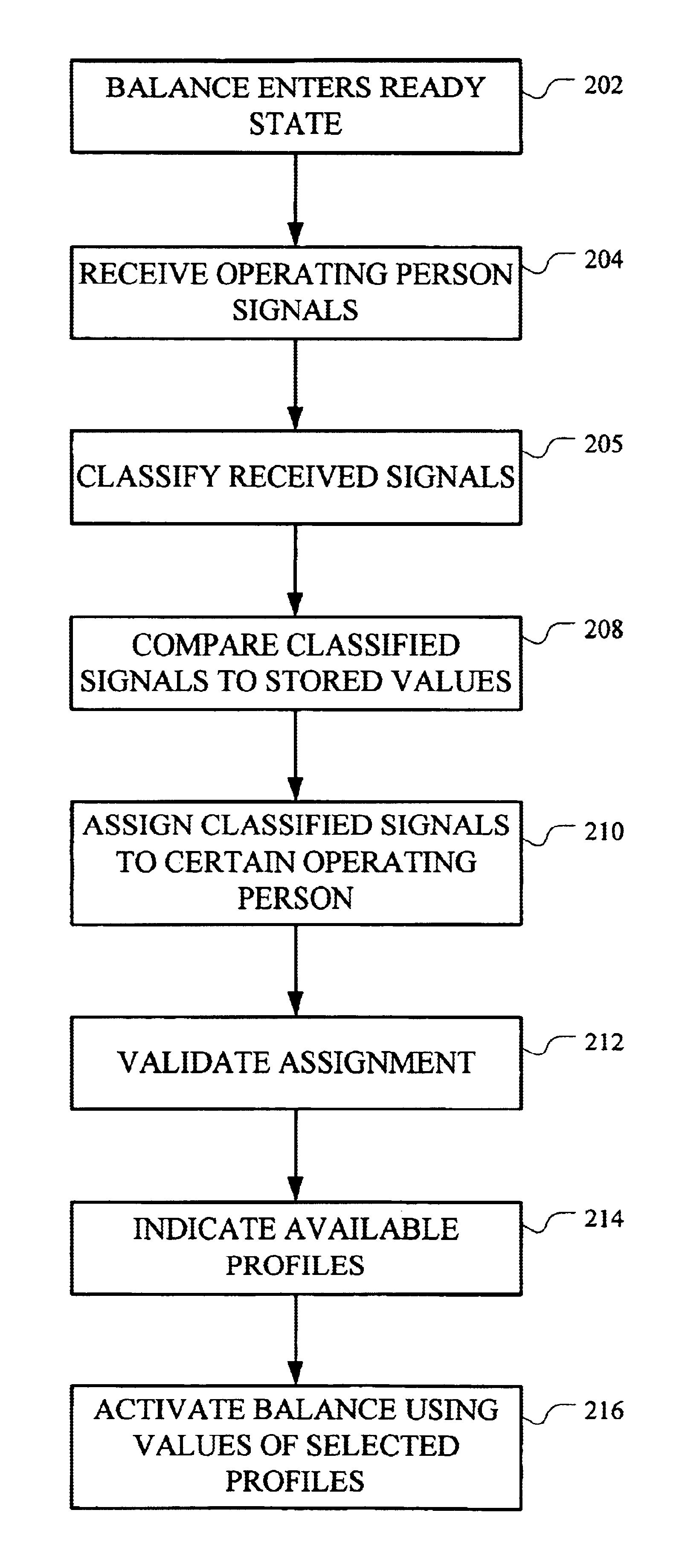
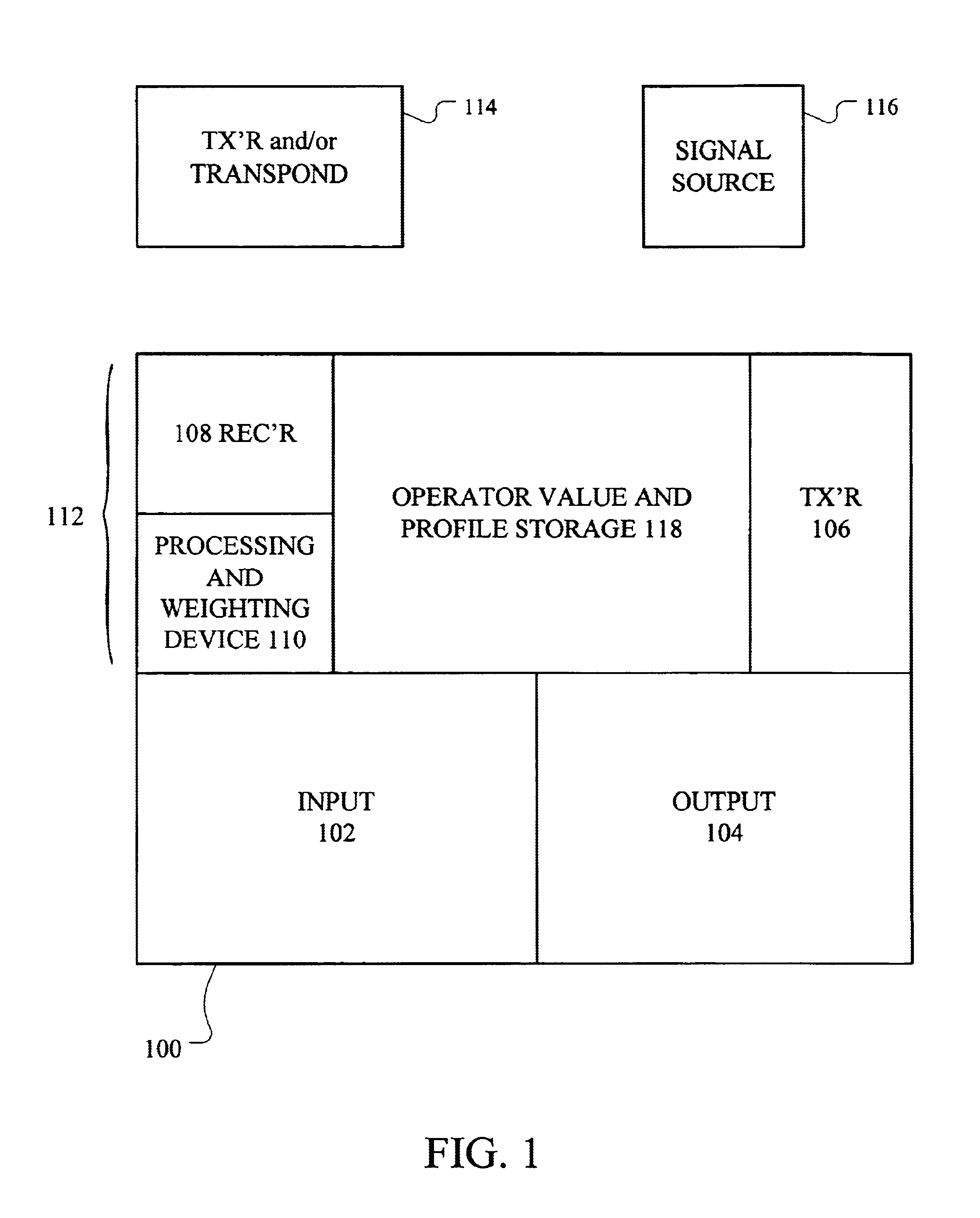
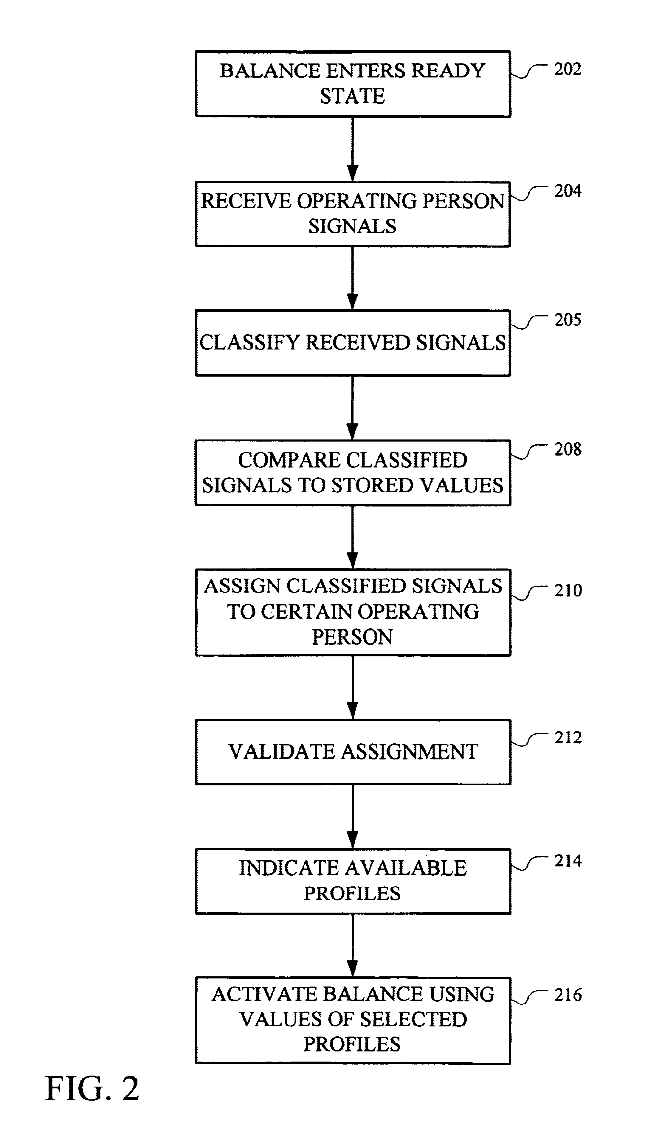
A representation of an exemplary FIG. 1 measuring apparatus 100 in a laboratory is an analytical balance, which can be of compact form and have at the front an input device 102 and an output device 104 which can collectively include an operating panel with a viewing screen in the form of a touch screen, and several touch keys. Such a balance is generally described in U.S. Pat. No. 4,676,327. Present as further elements in the input / output device can be, for example, proximity sensors, microphones, a loudspeaker, any suitable speech recognition processor and software, and / or any other desired input / output devices. The exemplary FIG. 1 measuring apparatus 100 also contains a transmitting / receiving device which can be attuned to passive transponders built into badges. The transmitting / receiving device can be configured as a transmitter 1...


PUM


Abstract

A measuring apparatus, for instance an analytical balance, can set parameter values for performing specific measuring tasks and/or for effecting communication with an operating person. Sets of such parameter values are stored as profiles. The measuring apparatus is equipped with a recognition device, for recognizing an operating person and activating a stored profile assigned to that person.

Description


Claims


Application Information

Patent Timeline
Owner METTLER TOLEDO GMBH
Learn More