Covering and mounting structure for a motion detector having light emitting diodes and electronic adjustment controls

a technology of light-emitting diodes and mounting structures, which is applied in the field of covering and mounting structures for motion detectors having light, can solve the problems of limiting the detection area covered by the sensor, damage or loss, and easy drop of masking materials, and achieves the effect of improving detection capability

Inactive Publication Date: 2005-01-18
IQ CORP. BV
View PDF3 Cites 21 Cited by
  • Summary
  • Abstract
  • Description
  • Claims
  • Application Information

AI Technical Summary

Benefits of technology

is to provide a covering and mounting ...

Problems solved by technology

The masking limits the detection area covered by the sensor.
These covers conventionally are separate plastic pieces which can easily drop off, get damaged or lost during installation, or during subsequent operation.
Whilst this solution may work, the masking material can easily be dropped...

Method used


Image

  • Covering and mounting structure for a motion detector having light emitting diodes and electronic adjustment controls
  • Covering and mounting structure for a motion detector having light emitting diodes and electronic adjustment controls
  • Covering and mounting structure for a motion detector having light emitting diodes and electronic adjustment controls

Examples


first embodiment

For clarity, alphabets “a”, “b” and “c” are used to differentiate the three embodiments. For the sake of explanation, the invention is elaborated in the form of a cylindrical telescopic covering and mounting structure 10a disposed in a pendant arrangement. The covering and mounting structure 10a is either wall-mounted or ceiling-mounted as shown in FIGS. 8 and 9, respectively.

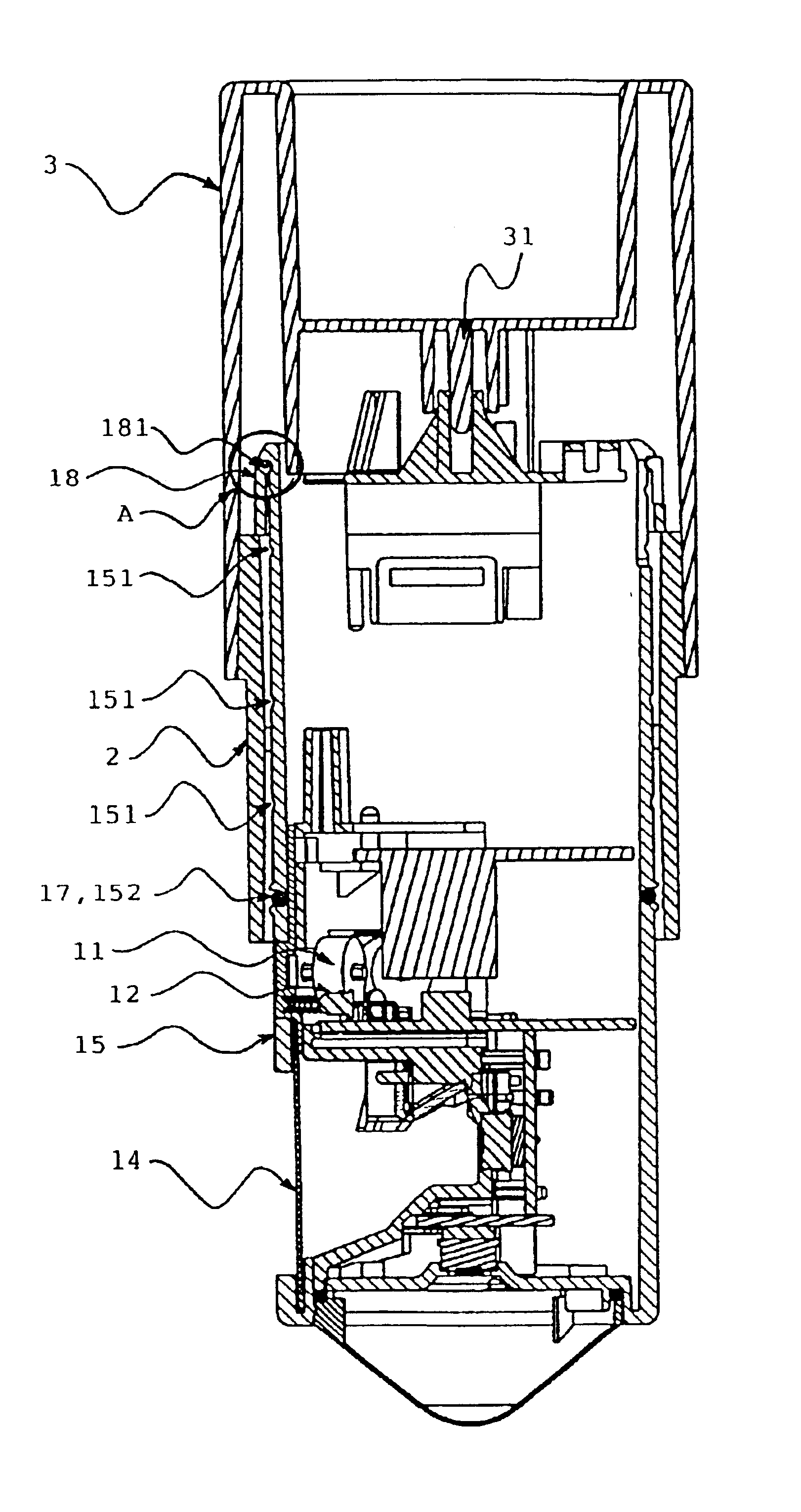
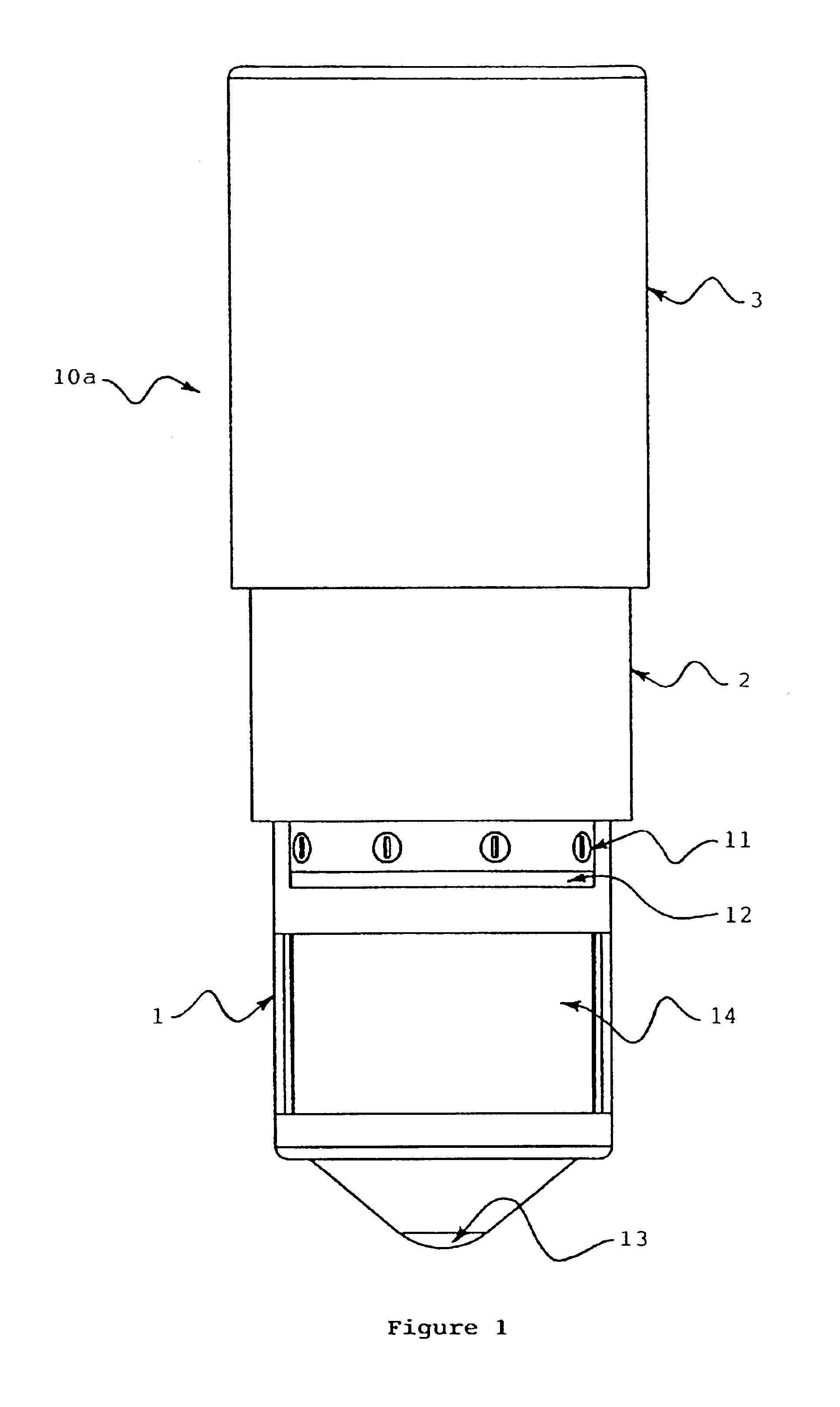
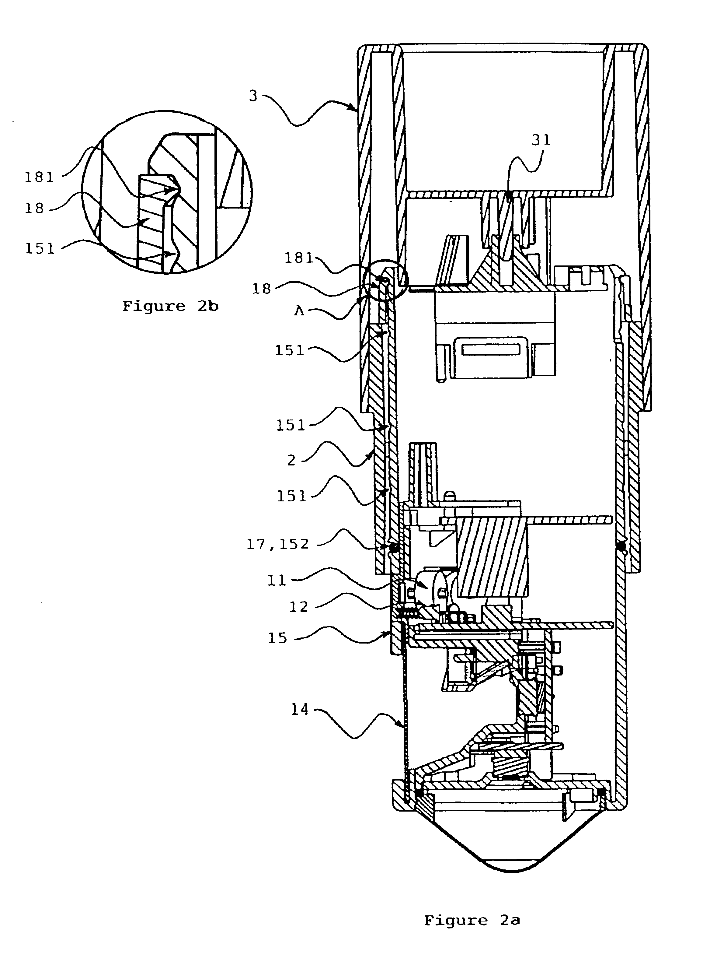
Referring first to FIGS. 1 and 2a, a cylindrical telescopic covering and mounting structure 10a is shown in its fully extended position. Electronic adjustment controls 11, LEDs 12, a second PIR motion detector lens 14 and a first motion detector lens 13 are carried on the covering and mounting structure 10a. The first motion detector lens 13 is downwardly viewing and provides a limited motion detection. The second PIR motion detector lens 14 is laterally viewing and provides wider motion detection.

The covering and mounting structure 10a comprises an inner tube 1 an intermediate tube 2 and an outer tube 3, and t...

second embodiment

A second embodiment is a single body cylindrical covering and mounting structure 10b, as shown in FIGS. 10a, 10b and 11. Since the covering and mounting structure 10b is not telescopic, an exterior covering structure 4 is employed to selectively mask the product features carried thereon. It is important to note that the shape of the exterior covering structure 4 must match and fit the shape of the mounting structure. Again, the second preferred embodiment can be disposed in a pendant or standing post arrangement. In the case of pendant arrangement, it is advantageous to include a downwardly viewing first motion detector lens 13 and a laterally viewing second PIR motion detector lens 14 for motion detection, according to the teaching of the invention. In the case of standing post arrangement, only a laterally viewing second PIR motion detector lens 14 is employed.

A third preferred embodiment of the invention depicts a telescopic cylindrical covering and mounting structure 10c dispose...


PUM


Abstract

A covering and mounting structure for mounting a motion detector having electronic adjustment controls, light emitting diodes (LEDs), and at least one motion detector lens, provides for selectively covering the controls, LEDs and a motion detector lens. The structure can be cylindrical or non-cylindrical in shape, and disposed in pendant or standing-post arrangement. Furthermore, the structure includes a telescopic structure or an exterior cover for the selective covering. In one embodiment, the structure includes one downwardly viewing first motion detector lens and a laterally viewing second PIR motion detector lens.

Description

TECHNICAL FIELDThe invention relates generally to a covering and mounting structure for a motion detector having light emitting diodes (LEDs) and electronic adjustment controls. It relates, in particular, to two motion detector lenses mounted on the covering and mounting structure disposed in pendant arrangement such that the covering and mounting structure allows selective concealment of the LEDs, electronic adjustment controls and motion detector lenses.BACKGROUND OF THE INVENTIONA motion sensor is typically mounted on a wall, eave, ceiling or post location. The sensor includes electronic adjustment controls with variable settings to adjust the electronic and / or optical performance of the product. Also included on the sensor are light emitting diode (LED) indicators, which indicate the electronic status of the product. Additionally, physical masking of a passive infra-red (PIR) lens on the sensor is included. The masking limits the detection area covered by the sensor. Furthermore...

Claims


Application Information

Patent Timeline
IPC IPC(8): G08B13/19G08B13/189
CPCG08B13/19G08B15/001Y10S250/01
Inventor BEASLEY, DANIEL JOHN
Owner IQ CORP. BV
Why Eureka
Try Eureka