Acoustic effect apparatus and method and program recorded medium therefor

a technology of acoustic effect and a program, applied in the direction of transducer details, instruments, electrophonic musical instruments, etc., can solve the problems of distortion of sounds, boosting unwanted bass tones, and failing to yield the intended effect of approaches

Inactive Publication Date: 2005-01-18
KORG
View PDF17 Cites 33 Cited by
  • Summary
  • Abstract
  • Description
  • Claims
  • Application Information

AI Technical Summary

Problems solved by technology

However, this approach fails to yield the intended effect unless the boosting of the bass tones takes place to a great extent.
If it is attempted to achieve a similar effect with a low capacity output amplifier and a small size loudspeaker, there results a distortion of sounds.
Furthermore, if a bass tone containing a component having a fundamental frequency of 110 Hz is concurrently input with a bass drum tone containing a component having a fundamental frequency of 100 Hz, the nonlinear circuit 17 would produce components representing both sum and difference between the both input signals, or 10 Hz component and 210 Hz component, resulting in boosting unwanted bass tones and producing sounds which are unmusical and granting.
As a consequence, overtones which are produced as a result of the non-linear conversion by the non-linear conversion table 22 include more of odd-numbered harmonics (overtones) than even-numbered harmonics (overtones), and it is noted that such a musical tone having an abundance of odd-numbered overtones disadvantageously leads to an indistinct and vacant timbre.
This, in addition to degrading the boosting of bass tones in a relative sense, results in a cross modulation when the plurality of varieties of alto and higher pitch musical tone data are input to the non-linear conversion table, producing components corresponding to differences and sums of frequencies among the plurality of alto and higher pitch musical tone data, that is, components which are not originally contained in the musical tone signal, and thus disadvantageously producing acoustic abnormalities in the auditory sensation.

Method used


Image

  • Acoustic effect apparatus and method and program recorded medium therefor
  • Acoustic effect apparatus and method and program recorded medium therefor
  • Acoustic effect apparatus and method and program recorded medium therefor

Examples


Embodiment Construction

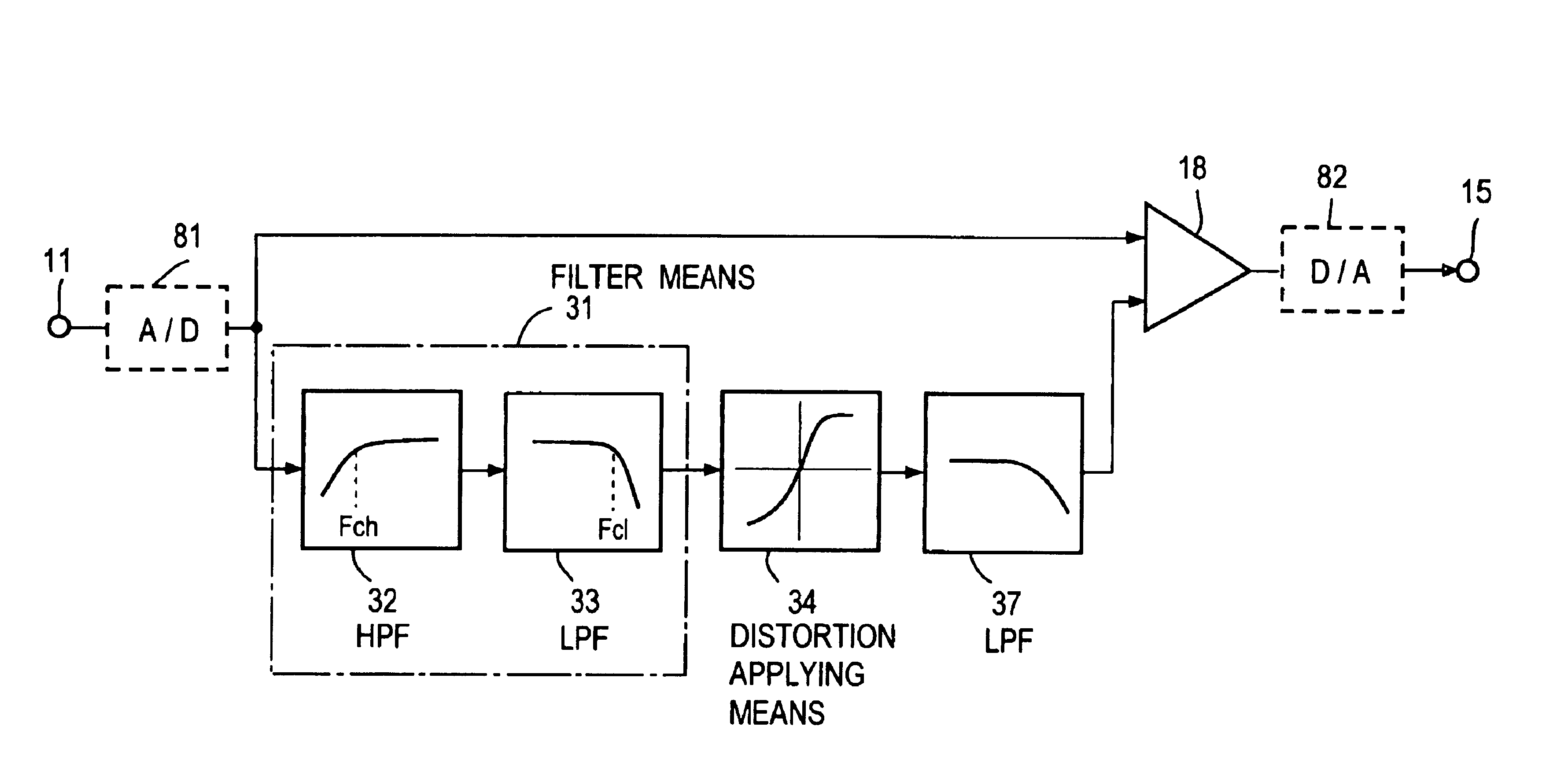
FIG. 5 shows an embodiment of the invention. An audio signal such as an output signal from a CD (compact disc) player (which may be a digital output signal), a rendition output signal from an electronic musical instrument, a rendition output signal from an electrical musical instrument, an output signal from a microphone which receives the sound of a music being played in an auditorium, a digital signal which is decoded from musical data transmitted by an electronic distribution is input to an input terminal 11.

Filter means 31 picks out the signals corresponding to double or higher overtones of a bass musical instrument such as a bass or a bass drum from the input audio signal from the input terminal 11. In the present instance, the filter means 31 only comprises a high pass filter (HPF) 32. The high pass filter 32 has a cut-off frequency Fch which depends on the variety of a musical instrument, for which the bass tones are to be boosted, and which lie in a range of 50˜300 Hz, but w...


PUM


Abstract

A high pass filter 32 having a cut-off frequency of 200 Hz and a cut-off response of +12 dB / OCT and a low pass filter 33 having a cut-off frequency of 400 Hz and a cut-off response steeper than −24 dB / OCT are used to pick out components in a double overtone region of 200˜400 Hz of a bass musical instrument such as a base or a bass drum from an input audio signal. The component which is picked out is input to distortion applying means 34 having an input-output response which is a non-linear response having no point symmetry with respect to 0 point, thus applying a distortion to cause even-numbered overtone components to be produced. An output from the distortion applying means 34 and the input audio signal are summed in a summer 18 to be delivered. Natural tones which have boosted bass tones and which are free from impurity are obtained.

Description

TECHNICAL FIELDThe invention relates to an apparatus and a method for imparting an acoustical effect by boosting a bass region of an audio signal such as a musical tone signal, and a program recorded medium used therefor.BACKGROUND ARTSome people desire to enjoy a physical sensation of a music in addition to listening to the music through the ear. A physical sensation of the music may be obtained by boosting bass tones to a higher loudness level. In the conventional practice of boosting bass tones, an equalizer is used to boost the bass region of an audio signal, and the boosted audio signal is amplified by a high capacity output amplifier, an amplified output signal of which is used to drive a gigantic woofer (loudspeaker used devotedly for the bass region). However, this approach fails to yield the intended effect unless the boosting of the bass tones takes place to a great extent. If it is attempted to achieve a similar effect with a low capacity output amplifier and a small size...

Claims


Application Information

Patent Timeline
Patent Type & Authority Patents(United States)
IPC IPC(8): G10H1/06G10H1/16G10H1/12
CPCG10H1/16G10H1/12
Inventor MOTOHASHI, HARUHIKOMORI, YASUHIKONAGASHIMA, MIKIO
Owner KORG
Why Eureka
Try Eureka