Auto rack car with end closure

a technology for auto racks and cars, applied in the direction of carriages, wagons/vans, building components, etc., can solve the problems of weakening the structural integrity of doors, and affecting the safety of doors

Inactive Publication Date: 2005-01-25
NATIONAL STEEL CAR
View PDF12 Cites 12 Cited by
  • Summary
  • Abstract
  • Description
  • Claims
  • Application Information

AI Technical Summary

Benefits of technology

In another aspect of the invention, there is an auto rack rail road car having a first deck upon which to carry wheeled vehicles, and a housing structure extending upwardly of the deck to define a space in which to shelter wheeled vehicles. The housing structure has a top chord distant from the deck, and a roof overspanning the first deck. The roof rises to a greater height than the top chord. The car has at least a first pair of radial arm doors operable to control access to the interior of the sheltered space. At least a first of the radial arm doors is movable on an arcuate path relative to the first deck, and the first door extends to a height greater than the top chord. The path of the first door is free of overhanging obstructions.

Problems solved by technology

A long standing concern has been the frequency of damage claims arising from vandalism and theft of the rail car cargo.
These openings may weaken the structural integrity of the door, making the door less secure.
In addition to possibly weakening the door, these slots might be used to insert a pry or other object to gain unauthorized access to the rail car.
The slots may also permit contaminants such as dirt and other foreign matter to enter the rail car, potentially damaging the rail car lading.
These ladders are preferably secured to the rail car body structure generally and are subject to vibration during operation of the rail car.
In cars in which the door extends past the height of the top chord to obstruct access to the gable end, the positioning of the brace may tend to present design challenges.
However this notch may tend to weaken the door and may also tend to permit dirt and other unwanted substances to enter the interior of the rail car.
It has been observed that multi-panel, hinged doors may tend to require more maintenance, and more care in operation generally, than rigid panel radial arm doors.
Further, each hinge, or opening, or crack may tend to provide a location at which vandals or thieves may seek access to the cars, or a point at which parts can be misaligned.
This uneven weight distribution may cause the roller assembly nearest the tangent portion to wear prematurely.
Difficulties may arise if forces transverse to the track are applied to the door.
For example, in the normal course of operation, the track may sag after years of operation under the weight of the door.
If the track sags, the rollers may tend to work their way off the track surface.
Alternatively, ice or some other obstruction may form or become lodged between the track and the roller.
If the extension becomes deformed then the door may not open and close properly.
Similarly, if the track itself is not adequately supported then the track and door may begin to sag with extended use, causing similar difficulties.
Even without obstructions or misuse of the door, the extension and track may wear out sooner than may be desirable if the track is constructed using relatively thin pieces of steel or other metal.
The roller and track arrangement described above may also leave a gap between the bottom edge of the door and the track.
The presence of dirt and debris in particular may inhibit the roller from rotating if the dirt becomes lodged between the roller and its axis, or may hasten wear.
Potentially damaging dirt and debris may also enter the rail car via gaps formed along the attachment interface between the rail car roof and the top chord of the wall assemblies.
This may tend to occur when a corrugated roof structure is used.
Although the door obtains some stiffness from its arcuate shape, the large door area may be relatively vulnerable to damage, and may be prone to relatively large deflections.
Given the area of coverage of the door, even a relatively thin shell of steel sheet may have a considerable weight, particularly when fitted out with locks, rollers and other door hardware.
Thus, it is undesirable to increase the general thickness of the door to obtain greater stiffness, since there is an inherent weight penalty.
However, it has been observed that welded reinforcements in doors may tend to be initiation sites for fatigue cracks, and even when repaired, may tend to crack again.
However, this did not necessarily prevent determined thieves or vandals from climbing over the top of the door to obtain access to vehicles carried on the highest deck.
A disadvantage in many of these cases is the need to notch the door to accommodate the ladder support structure as noted above.
Further, since the door tended not to be restrained at the roof line, the gable end portion of the door tended to be relatively weak.

Method used


Image

  • Auto rack car with end closure
  • Auto rack car with end closure
  • Auto rack car with end closure

Examples


Embodiment Construction

The description that follows, and the embodiments described therein, are provided by way of illustration of an example, or examples, of particular embodiments of the principles of the present invention. These examples are provided for the purposes of explanation, and not of limitation, of those principles and of the invention. In the description, like parts are marked throughout the specification and the drawings with the same respective reference numerals. The drawings are not necessarily to scale and in some instances proportions may have been exaggerated in order more clearly to depict certain features of the invention.

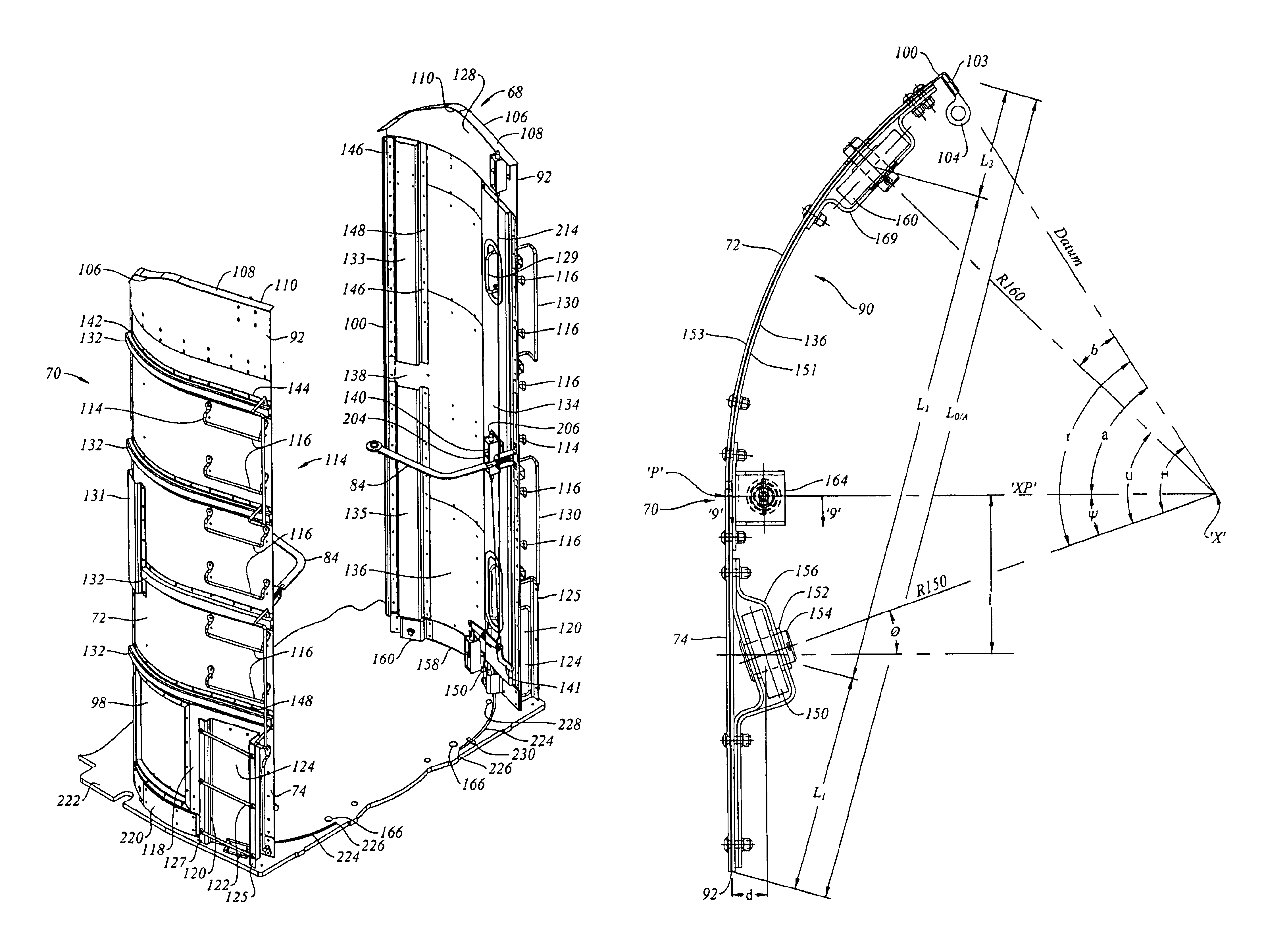
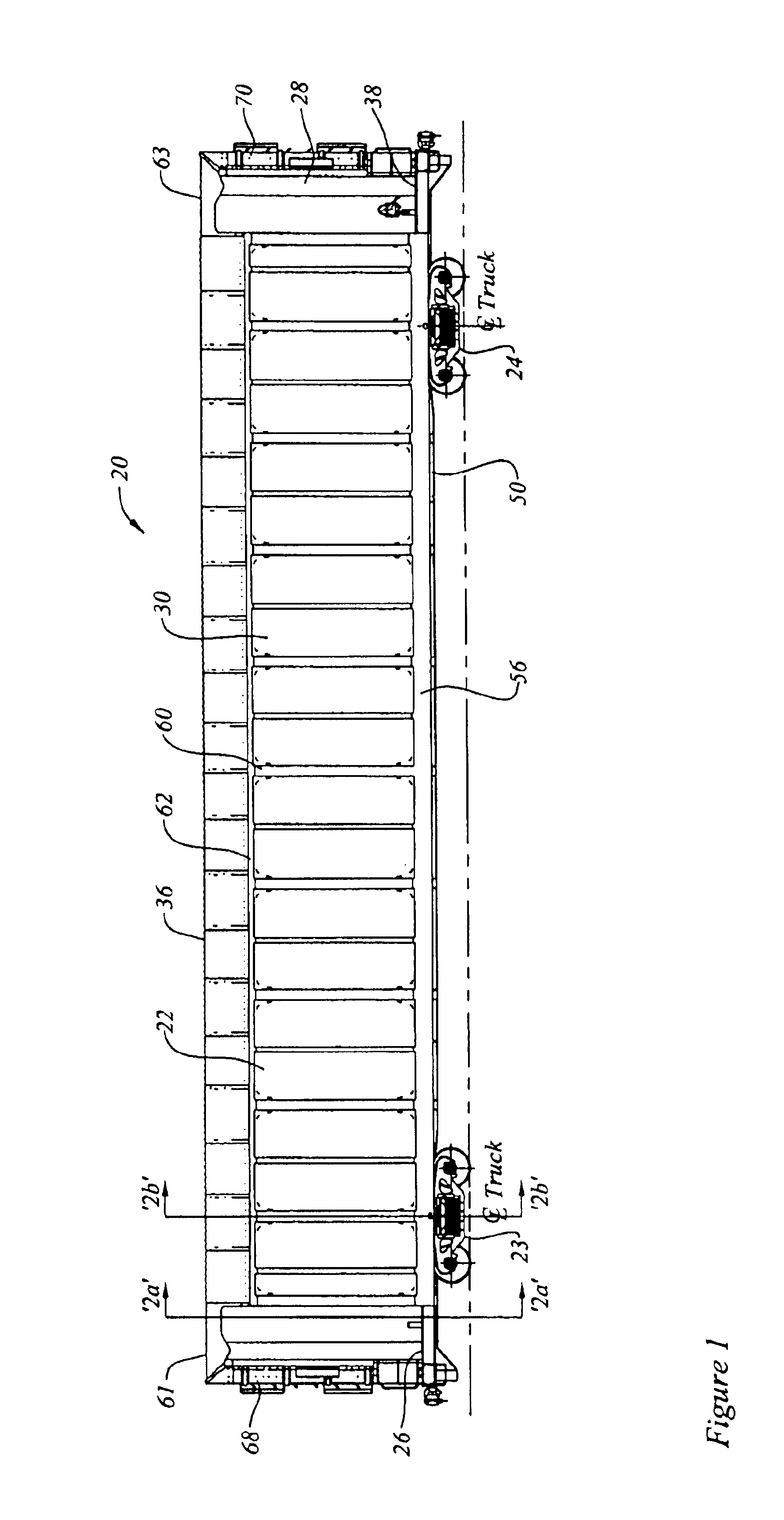
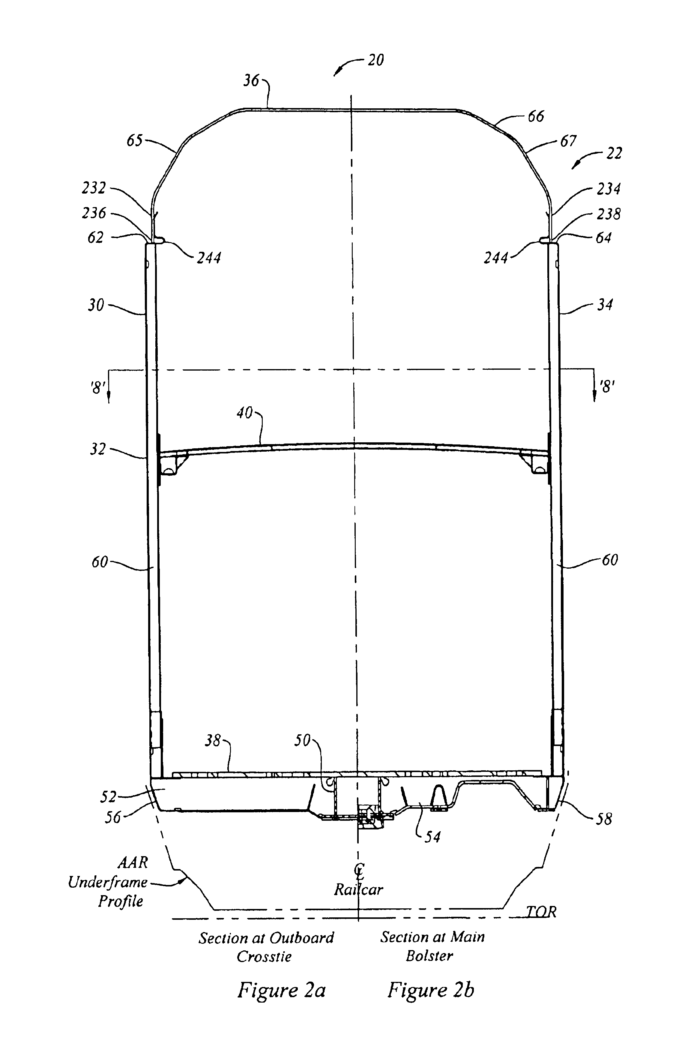
In terms of general orientation and directional nomenclature, for each of the rail road cars described herein, the longitudinal direction is defined as being coincident with the rolling direction of the car, or car unit, when located on tangent (that is, straight) track. In the case of a car having a center sill, whether a through center sill or stub sill, the long...


PUM


Abstract

An auto rack rail road car has a main deck and upper deck. It is provided with a door for controlling access thereto. The door is a radial arm door, and has a ladder mounted thereon by which personnel can ascend the second deck when the door is open. A second ladder is mounted to the first deck so that when the door is open the second ladder is positioned to co-operate with the first ladder. The arcuate path of the door is free from overhanging obstructions. The door also has internal and external weld-free stiffeners member for enhancing the rigidity thereof. A roller mounted to the door permits the door to be moved between open and closed positions. The door may further include a lock. A guide member protruding from the door co-operates with a groove in the main deck which slidingly guides the door as it moves between open and closed positions to control access to the car.

Description

FIELD OF THE INVENTIONThis invention relates to the field of auto rack rail road cars for carrying motor vehicles, and more particularly to doors for auto rack rail road cars.BACKGROUND OF THE INVENTIONAuto rack rail road cars are used to transport automobiles. They may be used to transport finished automobiles from a factory to a distribution center. A long standing concern has been the frequency of damage claims arising from vandalism and theft of the rail car cargo. Unauthorized access to the rail cars may be achieved by prying open the rail car access doors. The access doors of rail cars described in the prior art typically have slots or other openings to accommodate bridge plates, support structures or other obstructions. These openings may weaken the structural integrity of the door, making the door less secure. The slots or openings may also provide an opening in which to insert a pry bar to force the door open. An example of a rail car having a door with slots is described i...

Claims


Application Information

Patent Timeline
Patent Type & Authority Patents(United States)
IPC IPC(8): B61D17/04B61D19/00B61D17/06B61D3/00B61D3/18
CPCB61D3/18B61D19/004B61D17/06
Inventor FORBES, JAMES W.
Owner NATIONAL STEEL CAR
Why Eureka
Try Eureka